Observer-Based Fault Detection of Three-Phase Motor-Drive Systems
Jarod Delhotal with advisor A. Domínguez-García
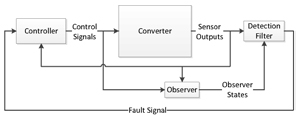
Figure 13: Block Diagram of System including Fault Detection.
Model-based methods have been applied to fault detection and isolation of linear systems. As switched-linear models can be used for dc-ac converters, we are using these models to develop an observer-based fault detection strategy for inverter-fed drives. A block diagram model of the system is shown in Figure 13. The observer-based technique allows for rapid detection and isolation of component faults, which in turn enhances the safety and reliability of the inverter-fed system.
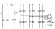
Figure 14: Circuit Model of Electric Vehicle Drive System
There are many applications for ac motor drives and inverters. I am currently focusing on applications for electric vehicles. The circuit model being used is shown in Figure 14. This model for an electric drive system consists of a battery, connections from the battery to the dc bus capacitor bank, six power semiconductors (here we assume IGBTs with reverse parallel diodes), and an electric machine (in this case an induction motor, including load).
This research is supported by the Grainger Center for Electric Machinery and Electromechanics.