Integration of End-winding Cooling and In-Slot Winding Cooling for High Power Density Electric Machines
CEME Collaborator Julia Zhang with Research Assistant Yanyan Xie at The Ohio State University
This project is jointly funded by the Grainger Center for Electric Machinery and Electromechanics and the Ford Motor Company. The objective is to study how to integrate end-winding and in-slot cooling and analyze the thermal performance improvement compared to a baseline traction machine that uses only the end-winding cooling.
Typical hybrid-electric vehicle traction electric machines apply spraying cooling methods, which is effective for cooling the end-windings. However, the majority of the winding conductor parts are buried inside the slots, with a limited heat-transfer path to the sprayed coolant. Thermal analysis shows that the conductors inside the slots can be exposed to high temperatures, which will stress the winding insulation and eventually cause insulation degradation and possible machine failure. This research focuses on the integration of the in-slot and end-winding cooling scheme to improve the performance of electric machine cooling systems. We developed a cooling scheme integrating end-winding cooling and in-slot cooling systems as shown in Figure 13
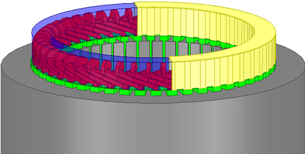
Figure 13: 3-D view of proposed electric machine cooling scheme
where the yellow piece is an end cap and the green pieces are cooling channels inside the slots. Red bars represent the hair-pin winding conductors. The cap and channels are adjoined to form one concealed cooling system covering all parts of the machine winding. The transparent blue part shows the coolant flowing around the end-windings.
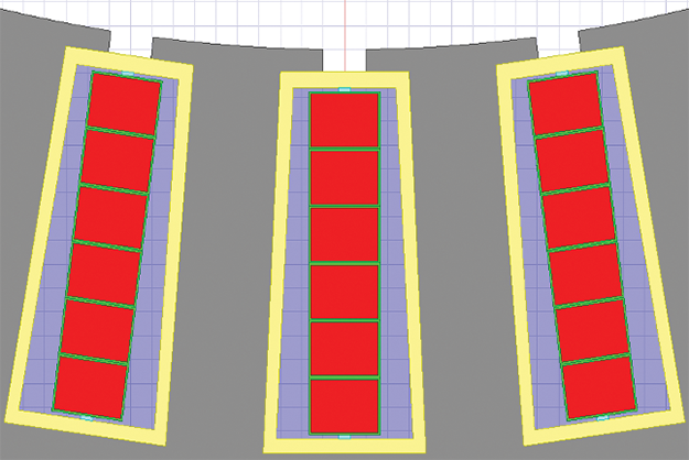
Figure 14: Cross section of electric machine stator with cooling channels
Figure 14 shows the cross section of this machine stator with the cooling channels in slots. The yellow trapezoids stand for the cooling channel walls and the transparent blue areas represent the coolant. In this design, the coolant has direct contacting faces with the heat source (machine windings), thus higher cooling efficiency compared to the end-winding spray cooling.
We investigated the manufacturability of this design including how parts should be assembled, materials for building the end-cap and cooling channels inside the slots, and how to seal the cooling channel without leaking. Figure 15 illustrates the first prototype built using 3D printing technology.
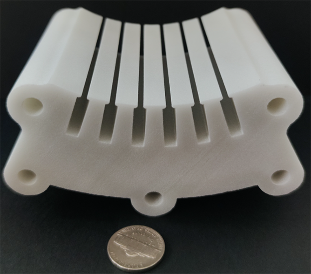
Figure 15: First prototype using 3D printing
Figure 16 shows the space for the end windings and Figure 17 presents a center hole where the cooling pipe will enter and a rectangular window for the winding lead to exit.
This first low-cost prototype, made of glass-filled nylon, is used to verify the part assembly, how to bend and install hair-pin windings, and determine if all the gaps can be effectively sealed without leaking. Once the concept is verified using this low-cost integrated in-slot and end-winding cooling prototype, we will build a second prototype made of silicon laminations to run thermal tests.

Figure 16: Space for the end windings
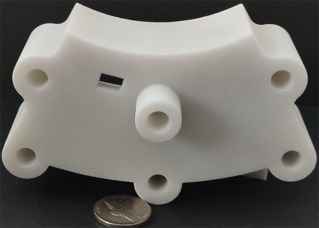
Figure 17 Center hole entrance for cooling pipe and rectangular hole exit for winding lead