Distributed Secondary Frequency Control in AC Microgrids with Lossy Electrical Networks
PhD student Siddhartha Nigam with advisors A. Domínguez-García and P. Sauer
The microgrid concept is a promising approach to enable efficient integration and management of distributed energy resources (DERs). In the microgrid islanded mode, frequency control is a major problem due to the prevalence of inverter-interfaced DERs leaving the microgrid with low or no rotating inertia. Secondary frequency control is key to insure the system-wide frequency returns to its nominal value following any change in the microgrid operating point. Most distributed secondary-frequency control schemes assume that all electrical lines in the network have an equal resistance to the reactance ratio, thus reducing the problem to controlling an electrically lossless microgrid. We propose a controller to account for ohmic losses in the electrical network with the distribution lines having unequal resistance to reactance ratios.
A controller hardware-in-the loop (C-HIL) testbed was used to test the distributed secondary frequency control scheme. The C-HIL testbed comprises an emulated islanded ac microgrid, whose components, i.e., the electrical network and the DERs and loads connected to it, are simulated using a Typhoon HIL real-time emulator. The model of the islanded microgrid is developed using high-order models of inverter-interfaced DERs. Monitoring and control of the DERs are achieved employing several interconnected Arduino micro-controllers, which implement our distributed algorithms for microgrid secondary-frequency control. Each Arduino micro-controller utilizes the information acquired, e.g., from measurements and information obtained through exchanges with other nearby Arduino devices, to perform successive computations and adjust the set points of the DERs it controls. The microgrid electrical network emulated on the Typhoon HIL real-time emulator and used for C-HIL testing of the distributed control scheme is shown in Figure 2. The rated capacity of the three DERs is 80 KVA, 70 KVA and 60 KVA, respectively, and the three microgrid loads are modeled as constant-power loads. We start the test with the load΄s active and reactive power demand set to zero. Afterwards, the total active power demand in the microgrid is increased by 10 kW, in one-minute intervals. When the proposed secondary-frequency control scheme is deployed, we see that the frequency error is fixed post any demand perturbation (see Figure 3).
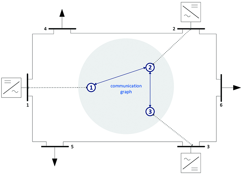
Figure 2. 6-bus microgrid, 3 control nodes communicating, as in Figure 3
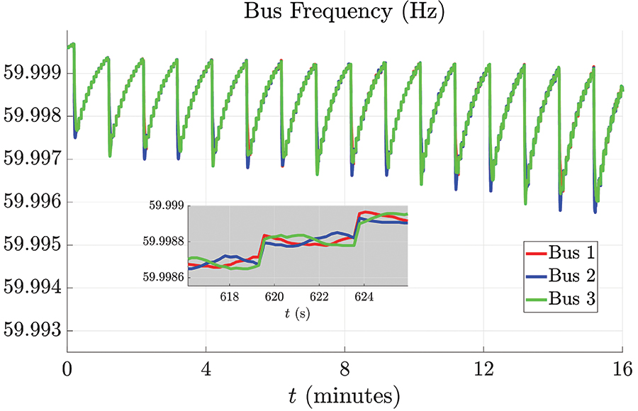
Figure 3. Frequency response with secondary-frequency control scheme