Cycloid Electric Machines for Robotic Applications
CEME Collaborator Professor Julia Zhang and Rui Liu – Oregon State University
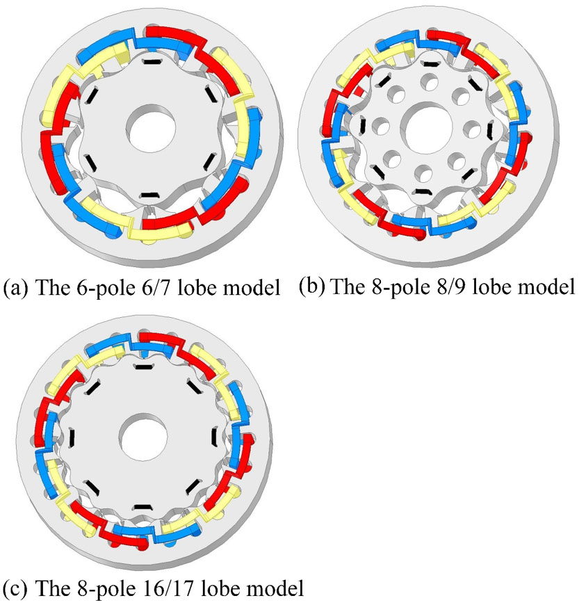
Figure 14: Different lobe number cycloid electric machine models. (a) 6-pole 6-rotor-lobe 7-stator-lobe model; (b) 8-pole 8-rotor-lobe 9-stator-lobe model; (c) 8-pole 16-rotor-lobe 17-stator-lobe model
The project objective is to verify the feasibility of a proposed robotics actuator shown in Figure 14, a cycloid electric machine that integrates an ac electric machine and a cycloid gear drive so that the size and weight of the conventional robotic leg actuation system can be reduced to achieve an improved torque density. The expected torque on the output shaft, which is connected to the cycloid rotor by several output pins inserted into the holes on the cycloid rotor, Figure 15 (b), is Nr times the torque on the cycloid rotor, where Nr is the number of lobes on the rotor. Three 3D models with different lobe numbers have been built and analyzed with SolidWorks and ANSYS, and the results are shown in Figure 15.
Figure 14 illustrates the 3D models with various lobe numbers: a 6-pole, 5-rotor-lobe model, an 8-pole, 8-rotor-lobe model, and an 8-pole, 16-rotor-lobe model. The outer diameter of the stator is 130 mm for each model, and the armature windings and magnets distribution are also illustrated. Figure 15 shows the simulation results of the three models. The excitation in the windings is a three-phase 40-Hz sinusoidal current. Unlike a traditional rotating electric machine, the center of the cycloid rotor follows a circle trajectory instead of a fixed point. No existing FEA tool is capable of simulating such a motion. Due to this limitation, the cycloid rotor is set to be stationary in simulations and the peak value of the torque is considered as the maximum output torque capability. According to the expected torque transmission, the output torque is proportional to the rotor lobe number. For example, on the premise of same poles number, when the rotor lobe number increases from 8 to 16, the output torque value should be doubled. However, the simulation results show that when the lobe number increases from 8 to 16, the output toque only increases from 9.5 Nm to 13 Nm.
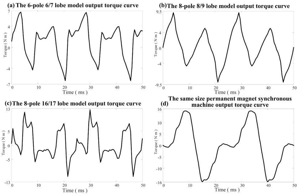
Figure 15: Cycloid electric machine models simulation results: (a) the 6-pole 6-rotor-lobe 7 stator-lobe model torque curve; (b) the 8-pole 8-rotor-lobe 9-stator-lobe model torque curve; (a) the 8-pole 16-rotor-lobe 17-stator-lobe model torque curve; (d) the same size permanent magnet synchronous machine torque curve
Further study reveals that that the gear ratio does not contribute to the torque transmission as the electromagnetic torque is generated on the output shaft instead of the input shaft, and that the torque on the output shaft equals the torque on the cycloid rotor. Thus, the proposed structure cannot proportionally amplify the electromagnetic torque as expected. In addition, the numerical results show the output torque of the proposed cycloid electric machine is only about 80% that of an interior permanent magnet synchronous machine (PMSM) with the same stator outer diameter and stack length.
The conclusions are that the performance of the proposed cycloid electric machine cannot compete with that of existing traditional PMSM, and that the cycloid electric machine cannot replace the traditional electric machine and gearbox for robotics applications. This research is supported by the Grainger Center for Electric Machinery and Electromechanics.