“Little Box” Challenge
“Little Box” Challenge
IEEE and Google announced the “Little Box” challenge in July of 2014 to encourage innovation in inverter technology. The goal is to create a 2 kW, single-phase, air-cooled inverter with a power density roughly 10 times smaller than current commercial products. Competing designs must meet a power density of at least 50 W/in3 and efficiency above 95%. The Illinois Little Box team, led by Assistant Professor Robert Pilawa-Podgurski, recently completed the first version of their prototype. Based on the quality and technical merit of their proposed design, the team was also the recipient of one of ten $30,000 development grants awarded by Google at the beginning of the competition.
The design of a single-phase inverter is complicated by the need to filter the twice-line-frequency power ripple which is drawn from the inverter output. The most common method for accomplishing this is to place several large (typically electrolytic) capacitors across the dc bus. Unfortunately, electrolytic capacitors can have relatively short lives due to electrolyte evaporation. In order to increase system life, film or ceramic capacitors are being explored for energy buffering applications. Because these technologies are costly and often have lower-than-desired energy efficiency, they are frequently used in conjunction with a power converter which allows the capacitor voltage to swing widely while maintaining a stable dc bus voltage at the inverter input. The Illinois team has developed a series-stacked, partial power processing ripple-compensating converter shown in Fig. 1. It utilizes ceramic capacitors in a series-stacked configuration to
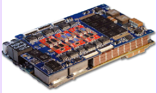
Figure 1: Photograph of the flying-capacitor multilevel converter inverter board and energy buffer fit together
maintain a dc bus voltage ripple of less-than 2% while maintaining a round-trip efficiency of 99.3%.
The dc-ac inverter employs a seven-level, flying capacitor multi-level inverter to reduce the size of filtering components. The multilevel architecture increases the effective ripple frequency seen at the filter inductor and therefore significantly reduces the inductor
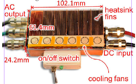
Figure 2:Photograph of the inverter prototype inside the heat-sink and enclosure
size. In addition to a multilevel architecture, the inverter uses high efficiency, power-dense GaN switches which are integrated into custom half-bridge modules for increased power density and efficiency. A picture of the current inverter prototype is shown in Fig. 2. With rectangular dimensions of 4.02 in x 2.42 in x 0.95 in and a total volume of 9.24 in3, the experimentally verified power density is 216 W/in3. A peak efficiency of 97.6% is achieved, including the power losses from control and cooling fan.
Since the submission of the technical approach document on July 22nd, the team has been focused on further reducing the inverter volume and optimizing the design to meet the competition specifications. The final inverter design will be submitted for 100 hours of testing at the National Renewable Energy Laboratory. The one million dollar, grand prize winner will be announced in January 2016.
Concepts developed in this “Little Box” project are being employed in designing high-density inverters for photovoltaic and motor-drive applications.