Electrical Battery Model for Use in Dynamic Electric Vehicle Simulations
Electrical Battery Model for Use in Dynamic Electric Vehicle Simulations
Yue Cao with adviser P. Krein
Simulation of electric vehicles over driving schedules within a full dynamic electric vehicle simulator requires battery models capable of accurately and quickly predicting state-of-charge (SOC), I-V characteristics, and dynamic behavior of various battery types. An electric battery model utilizing multiple time-constants, including ranges of seconds, minutes, and hours, is developed. The model parameters include open-circuit voltage, series resistance, and equivalent RC circuits, with nonlinear dependence on battery SOC. The proposed model for predicting terminal voltage and power losses of lithium-ion (Li-ion), nickel-metal hydride, or lead-acid battery batteries is shown in Fig. 30. The SOC captures effects from discharge and charge rates, temperature, and battery cycling. A systematic and generic methodology for parameter extraction is explained as well as obtaining SOC factors through reasonable test work when evaluating any given battery. Experimental parameters found from bench tests characterize the Panasonic CGR18650 Li-ion cells sufficiently and exemplify methodology to test other batteries. Thermal modeling predicting real-time battery temperature is introduced. Lack of substantive terminal behavior much faster than seconds is validated through testing. A Li-ion battery model is programmed into MATLAB/Simulink and used as a power source for an existing comprehensive dynamic vehicle simulator. A battery testing apparatus is designed for validation of the model with hardware-in-the-loop driving schedule cycling of real batteries. The simulated SOC, terminal voltage and output power response to the Federal Urban Driving Schedule (FUDS) and another formulated city/highway driving schedule tracks the measured responses. Figure 31 displays the simulated and measured individual Li-ion battery’s output power from a window of the 22-min FUDS drive cycle. The battery model supports extensive tests to estimate efficiency and losses within a battery pack during various driving schedules and vehicle dynamic operation strategies.
This research is supported by the Grainger Center for Electric Machinery and Electromechanics.
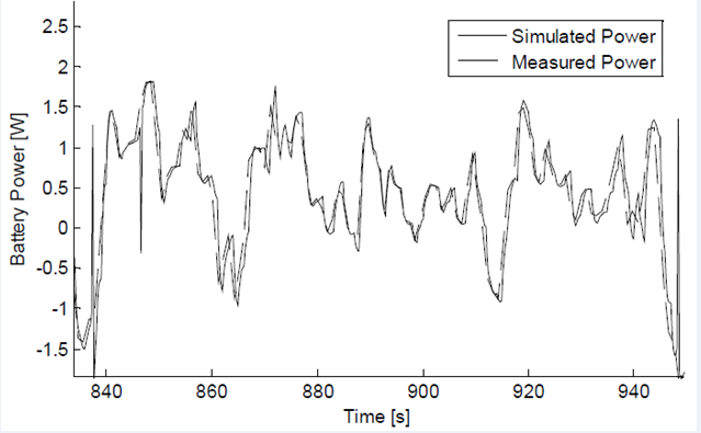
Figure 31: Simulated and measured battery power across FUDStric Machinery and Electromechanics.
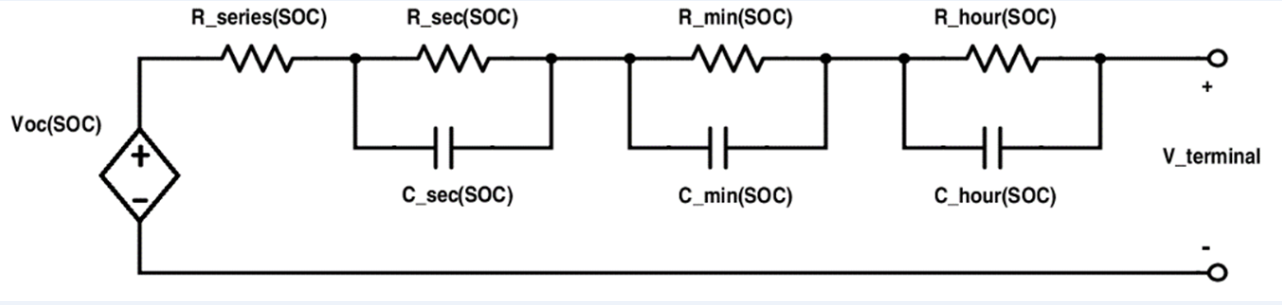
Figure 30: Multiple time-constant approach model for battery terminal voltage and losses