System-Based Design of a Grid-Tie Motor/Generator Set and Drive
Professors Ted Brekken and Annette von Jouanne, Oregon State University, Electrical Engineering and Computer Science, Wallace Energy Systems and Renewables Facility, Corvallis, OR
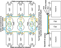
Figure 9: Power block assembly.
This Grainger collaborative network student funding is directed toward the system-based design of a grid-tied 50kW doubly-fed induction machine (DFIM) and drive for adding inertia and stability to microgrids. In this design, a DFIM tied to our lab 3-phase 480 V, 750 kVA dedicated utility supply, is driven to vary its rotational inertia to test its effect on microgrid stability. Simulation models have been created using Mathworks Simulink and model-based design software to verify operational characteristics using the selected power electronic components. The electronics of a custom power block assembly have been designed as shown in Figure 9. The power block assembly groups the required IGBTs, gate drivers, dc-bus capacitors, and thermal management components for the drive and energy storage converters into an efficient compact unit. The assembly incorporates two dc-bus connected 480V 3-phase inverters capable of sourcing or sinking up to 50kW.
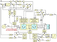
Figure 10: Energy storage simulation block diagram.
A specialized custom embedded controller has been designed that permits precise monitoring and control of the power block assembly. The controller design allows a PC connected via an Ethernet, CAN bus, or MODBUS interconnection to control and monitor the DFIM operation and associated energy storage at a speed and accuracy sufficient for detailed critical analysis. The design encloses the custom controller and all power electronics (excluding the DFIM and grid isolation transformer) within a 36” x 24” x 72” NEMA 12 certified enclosure.
This work included detailed simulations to verify system operation, reactive component specifications and controller design. One of the simulation models used is illustrated in Figure 10. Through simulation efforts, design modifications were made to reduce ripple currents and to accommodate the high currents to and from the 300V 83 Farad energy storage supercapacitor bank.
This work is funded by the Grainger Center for Electric Machinery and Electromechanics
and the University of Illinois SURGE Fellowship.