Real-Time Low-Level Simulation of Hybrid Vehicle Systems for Hardware-in-the-Loop Applications
Marco J. Tavernini and Benjamin Niemoeller with adviser P. T. Krein
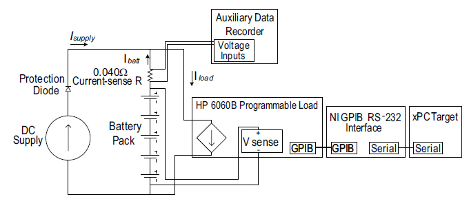
Figure 12: Diagram of GPIB-based HIL battery interface.
Choices of battery pack, motor drive, drive train control strategy, and the effects of these choices must be considered for any electric or hybrid vehicle (HV) design. Factors to be considered include range of the vehicle on a single charge, battery life, engine operating tradeoffs, and some combination of maximum output drive power for a given battery pack size. Hardware-in-the-loop (HIL) simulation can address many of these issues. The current project advances prior work to bring a comprehensive low-level HV simulator up to real-time performance and enable it to manage HIL studies.
Dynamic simulation is essential for loss evaluation and to test the impact of fast current and voltage transients on major components. Consider the behavior of a vehicle during rapid acceleration. Large power demands increase currents in a manner dependent on motor resistive drops, flux settings, inverter drops, battery state of charge, and other losses in the vehicle. This in turn decreases the available bus voltage. The motor control will react to maintain power delivery to the motor, further increasing the current and system losses. Thermal hot spots and peak battery stresses result from the give and take during these interchanges and have profound design implications.
A Simulink model was adapted to run in real time on a dedicated PC running the xPC Target operating system. The dynamic model requires computation of instantaneous motor-phase current. To calculate a sinusoidal waveform of several kilohertz bandwidth with a fixed-step ordinary differential equation solver, all states within the Simulink model must be computed every few microseconds. Optimizations on both the software and hardware side allowed the maximum time at which the model was stable to be increased from eight to 11 μs. and the dedicated PC to run the model in real-time with the required 11 μs step size.
An interface between the simulation computer and a battery pack was also tested. A programmable dc load, biased by a fixed-current dc supply, was used to charge and discharge the battery during a simulation trial, as shown in Figure 12. In turn, the battery voltage was measured and sent back to the model. The HIL computer scales voltages and currents so that the full-sized pack in a vehicle may be represented by the small pack under test. Simulated and experimental results were compared and fell to within 1% of each other. With this platform verified experimentally, the door is open to more extensive analysis of both drive train and auxiliary systems. In addition, the HIL model can be applied to different vehicle types, including underwater and airborne systems, as well as other classes of ground transport vehicles.
This work is supported by the Grainger Center for Electric Machinery and Electromechanics.