Modeling and Control of a Microinverter for Alternating-Current Photovoltaic Modules
Trishan Esram with adviser P. L. Chapman
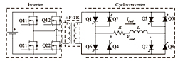
Figure 27: Proposed topology for microinverter.
Alternating-current (ac) photovoltaic (PV) modules have the potential of bringing down the upfront unsubsidized costs of installed PV systems. Unlike regular PV modules, ac PV modules embody relatively smaller inverters, often called microinverters, to directly output ac power, which can be used by local loads and fed into the utility grid. A topology (Figure 27), initially proposed for fuel-cell applications, lends itself well to ac PV module microinverters. The operation of this topology, which uses an innovative state machine control for proper current commutation, has been proven both in hardware and simulation, as shown by the waveforms and logic signals in Figure 28.
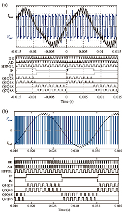
Figure 28: Experimental (a) and simulation (b) waveforms and logic signals.
To fully understand the potential of the proposed topology as an ac PV module microinverter, a PV module has to be used as the source and the utility grid as the load. Consequently, additional controls are needed to track the maximum power point of the PV module and to interface with the utility grid, while meeting all the regulatory codes and standards. To formulate and test appropriate control algorithms, a theoretical model for the microinverter
will be derived. The behavior and performance of a grid-tied PV system, having several ac PV modules in parallel, will then be investigated by using several such microinverter models, along with the required controls.
This work is supported by the Grainger Center for Electric machinery and Electromechanics.