Mechanical Analysis of a high-speed motor
Lijun Zheng with adviser K. Haran
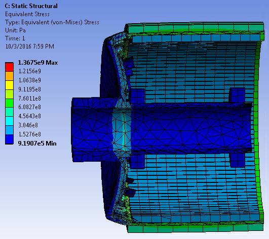
Figure 10: ANSYS motor rotation simulation showing need to increase magnet and rotor length by 0.7 inch
This project goal was to refine our motor’s mechanical design in three areas: deflection/expansion, airflow, and vibration. To meet these goals, we employed ANSYS simulation software and collaborated with Dr. Ahmed Taha in the National Center for Supercomputing Applications. Using ANSYS mechanical simulations, as shown in Figure 10, we found that the magnet length and machine size should be increased by 0.7 inch. Then models were calibrated with results from mechanical tests on a full size rotor that was spun up to 18,000 rpm at a test facility in Massachusetts. Based on these results, an updated rotor dynamics analysis simulation using XLRotor for the model was performed. Collaboration with Dr. Taha involved evaluation fan performance. ANSYX simulation software was used develop computational fluid dynamics, and an ANSYS CFX analysis was constructed to simulate rotation airflow, as shown in Figure 11. An XLRotor model was constructed to test rotor and design dimensions to find the natural frequency map and improved Ip/It (polar moment of inertia/transverse moment of inertia) ratio for motor vibration and dynamic performance, as shown in Figure 12. These analyses confirm that the final 1 MW motor design would function well at the desired operating point. This research was supported by the Grainger Center for Electric Machinery and Electromechanics.
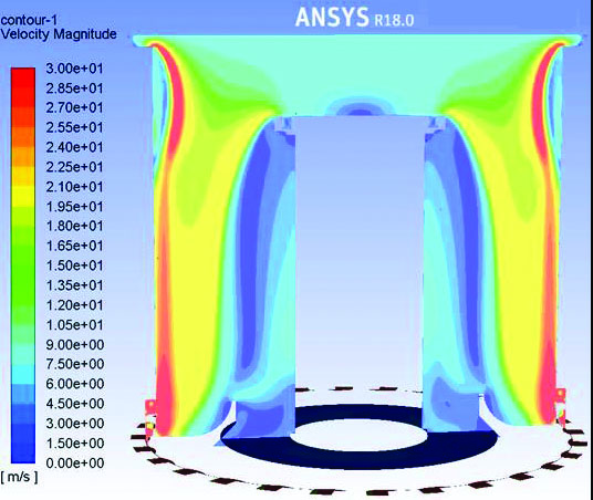
Figure 11: ANSYS CYX analysis to simulate airflow due to rotation
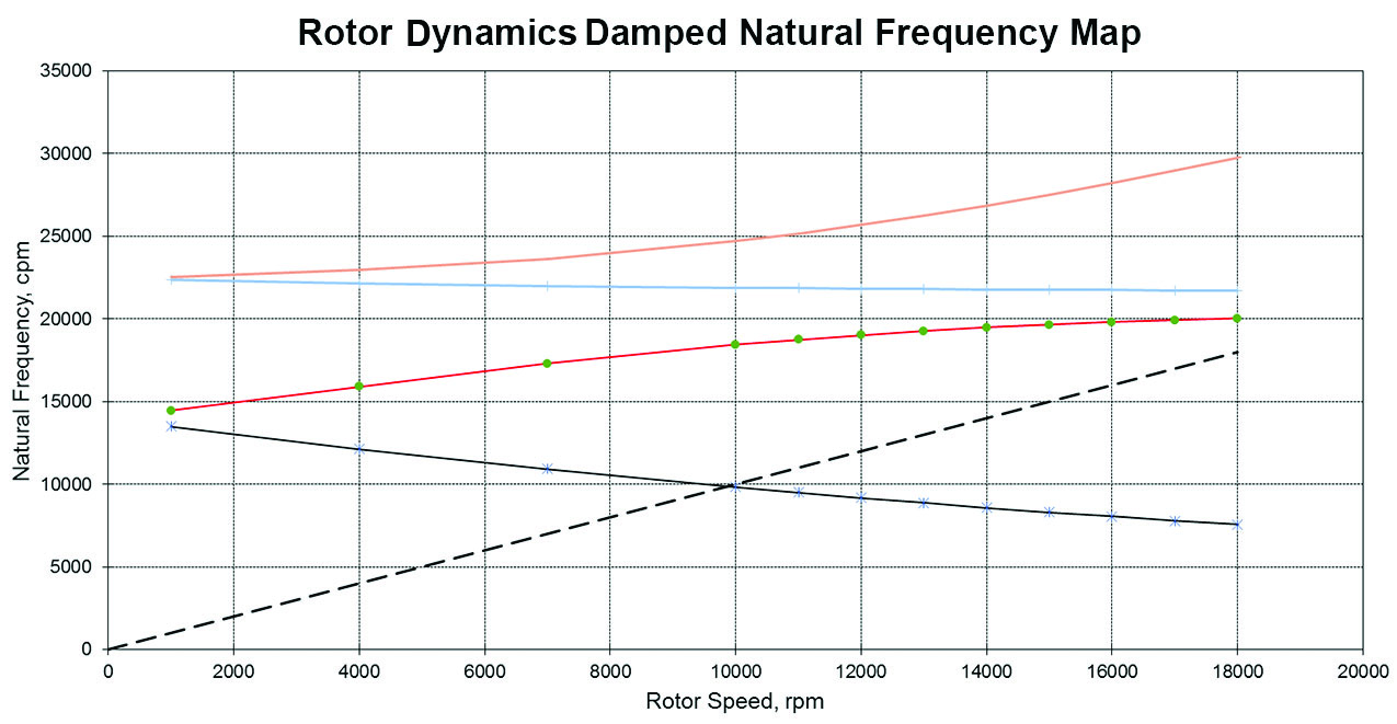
Figure 12: Rotor dynamics damped natural frequency map on XLrotor to measure vibration