Low-Cost Rapid Wide-range Adaptive Drives Using Arduino or FPGA
Yichao Tian, M.S. student of University of Michigan Ann Arbor
Julia Zhang, The Ohio State University
The objective of this proposed research is to set up two rapid wide-range adaptive drives using low-cost controllers. One platform uses an Arduino control unit and the other uses an FPGA controller to sense and control a permanent magnet synchronous machine, when supplied by a traditional three-phase 2-level dc-ac inverter.
Commercial drive controllers typically use digital signal processors or microcontrollers manufactured by OEMs such as Texas Instruments and Motorola, etc. These digital controllers provide powerful hardware and software functions for motor drive control but also require new learners tremendous time and effort to become experts. Arduino is a low-cost open-source microcontroller platform with simpler hardware and software compared to the abovementioned powerful digital controllers. An FPGA is an integrated circuit that can be programmed by users to achieve powerful circuitry, calculation, and control functions. Digital controllers including Arduino use sequential execution where each line of code executes in the order in which it is listed. While an FPGA is capable of both executing many functions simultaneously and sequential execution. Applying FPGAs to motor drive control may help improve the motor drive control performance.
The Arduino system as shown in Figure 27 includes an Arduino UNO R3 microcontroller, an Arduino SimpleFOCShield v2.0.4 motor driver (12 V to 35 V input dc, 5 A peak current), and a permanent magnet synchronous machine (PMSM) motor, Gimbal 2805/100KV. The PMSM motor is rated at 7 V and 1.5 A. The motor has an integrated 12-bit on-axis magnetic rotary position sensor AS5600. The entire system is less than $60. The FPGA system as shown in Figure 28 includes an Altera DE2-115 development board, a three-phase motor drive using TI DRV8302 (5.5 to 45 V input dc, 15 A output current), a 3000-rpm, 64-W PMSM 42JSF630AS-1000 integrated with an incremental encoder 1000 PPR. The FPGA development board unit price is about $700. The result of the hardware system costs less than $150.
The following control algorithms were developed for both the Aruidno system and FPGA system: space vector pulse width modulation, three-phase current sensing, rotating reference frame transformations, current feedback control, rotor angle and speed calculation, speed feedback control. Figures 29 and 30 show the command speed and feedback speed for the Arduino system and FPGA system, respectively. Fast speed transient operations were used to simulate the load testing. If only motor control related functions and peripheral circuits are needed for the FPGA chip, the controller board can be much more simplified, and the cost can be significantly reduced. Both systems can achieve basic motor drive control functions without any issues. The team only had enough time and resources to test the systems using small-size PMSMs and did not have time to try induction machines.
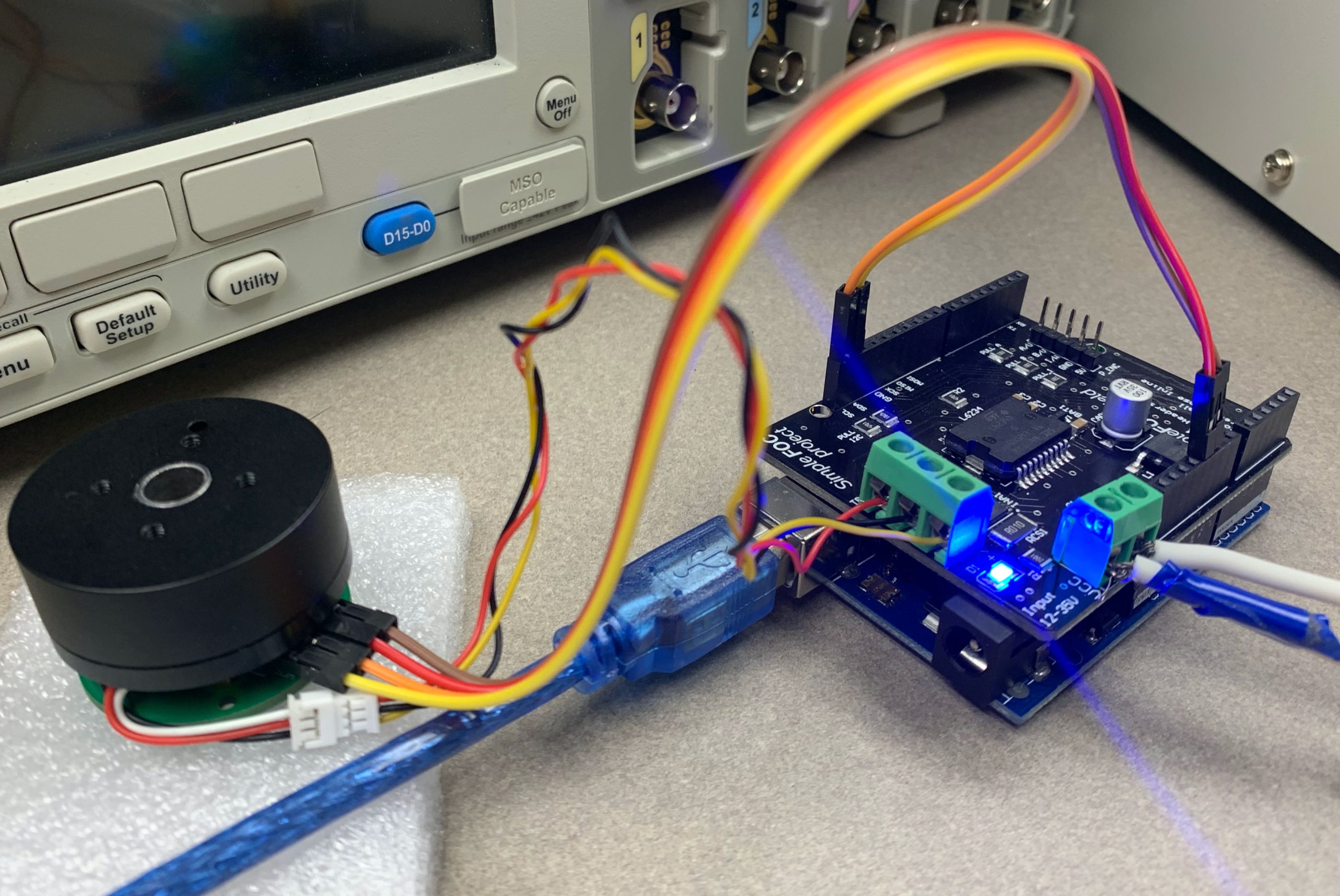
Figure 27: Arduino system
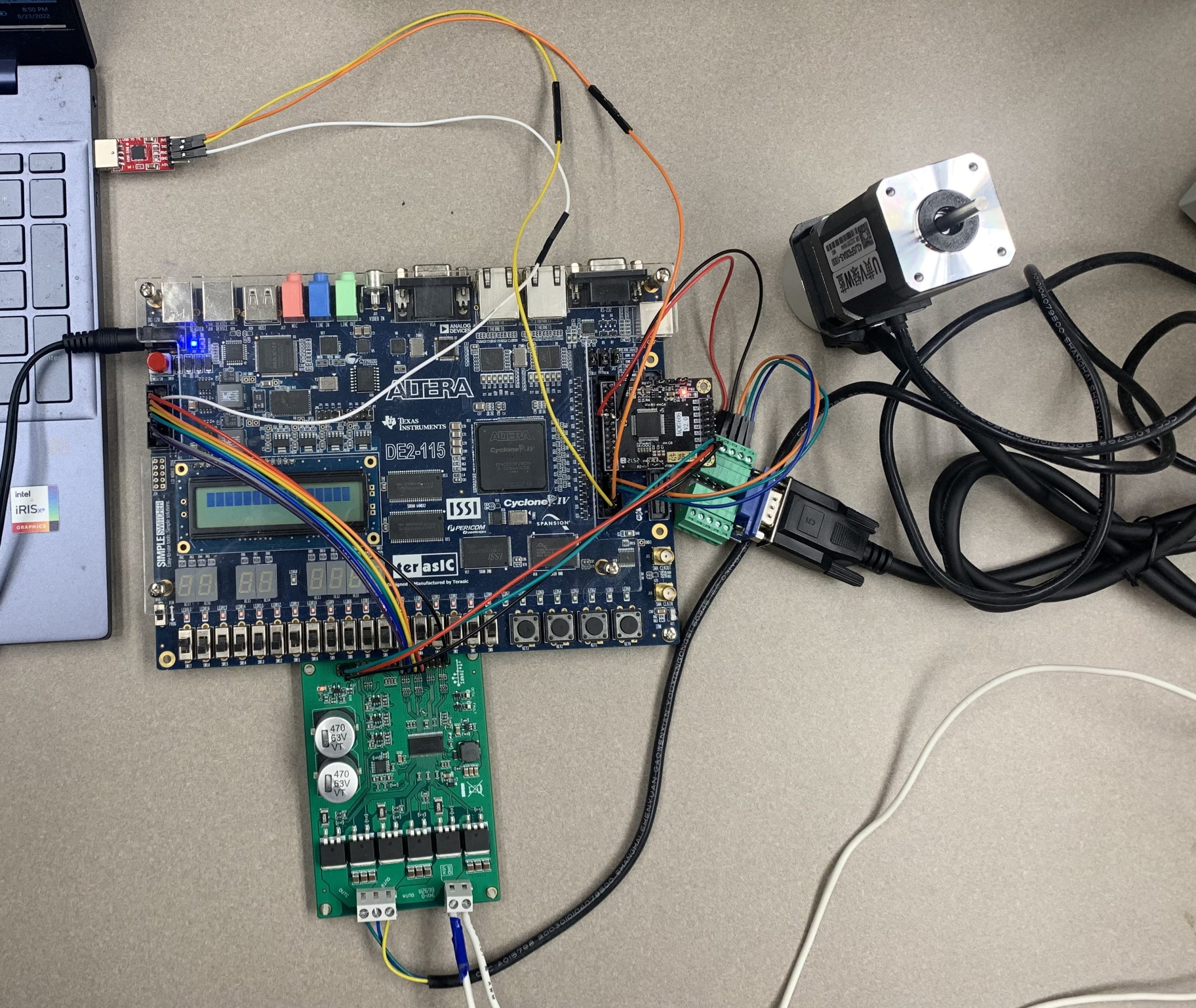
Figure 28: FPGA system
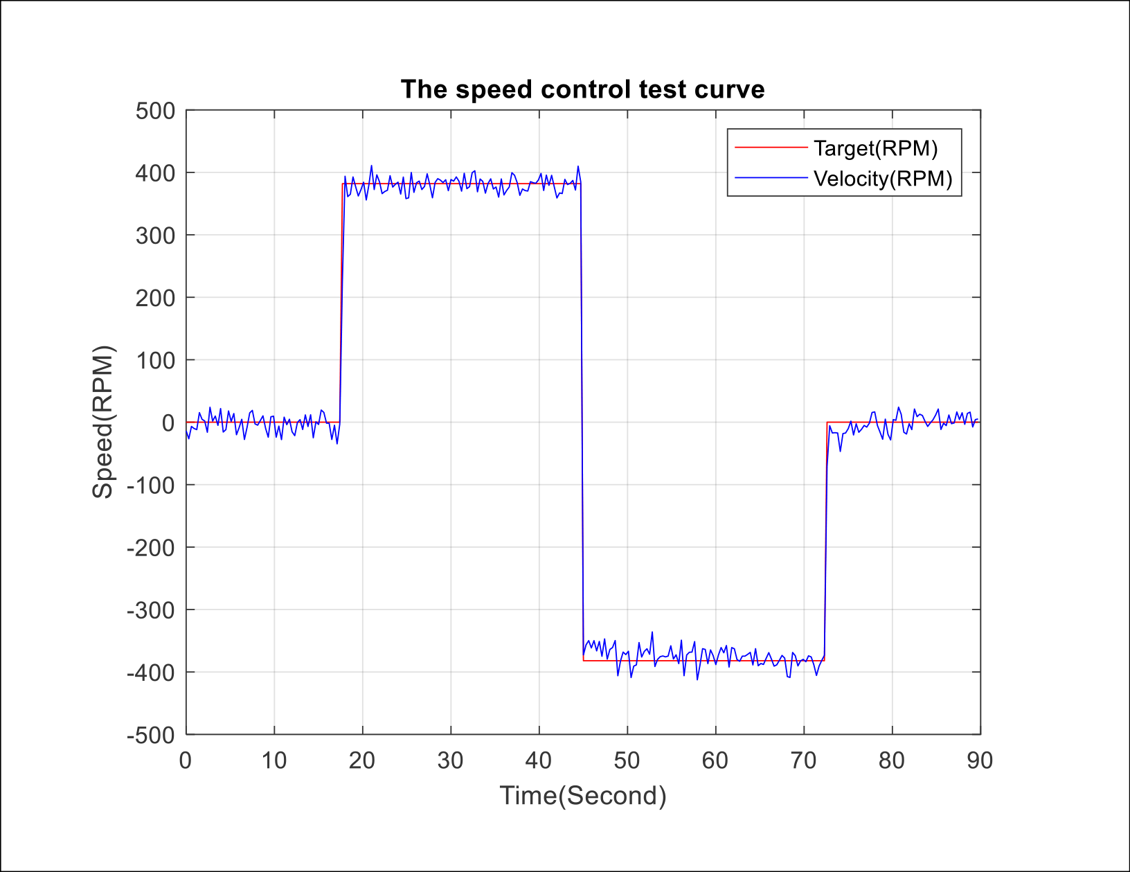
Figure 29: Command and feedback speeds for the Arduino
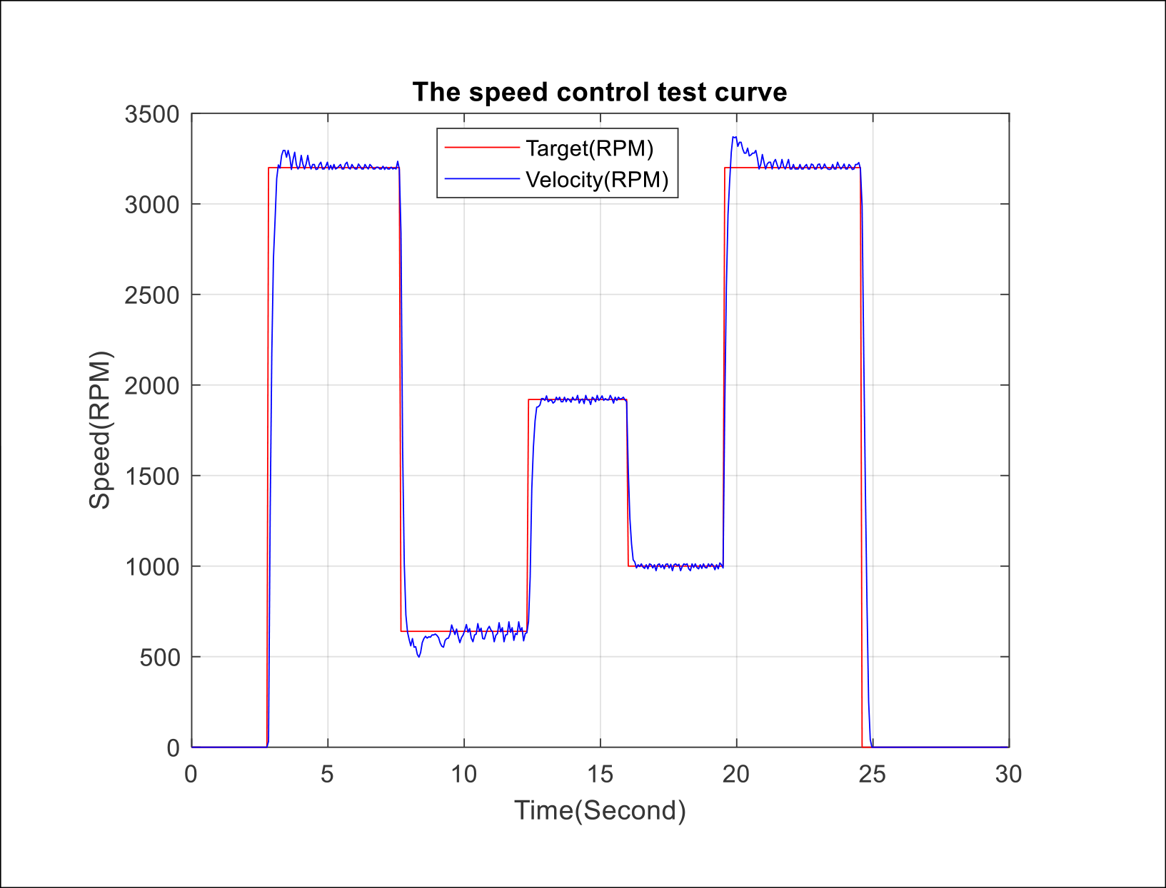
Figure 30: Command and feedback speeds for the FPGA