Low-Cost Rapid Wide-range Adaptive Drives Using Arduino and FPGA
CEME Collaborator Julia Zhang with Qaed Alosaimi The Ohio State University
This research is funded by the Grainger CEME. The objective of this proposed research is to set up two rapid wide-range adaptive drives using low-cost controllers. One platform uses an Arduino control unit and the other uses an FPGA controller to sense and control a permanent magnet synchronous machine, when supplied by a traditional three-phase 2-level dc-ac power converter.
Commercial drive controllers typically use digital signal processors or microcontrollers manufactured by companies such as Texas Instruments and Motorola. These digital controllers provide powerful hardware and software functions for motor drive control and require a high learning curve to operate. Arduino is a low-cost open-source microcontroller platform with simpler hardware and comparable software. An FPGA is an integrated circuit that can be programmed by users to achieve powerful circuitry, calculation, and control functions. Digital controllers, including Arduino, use sequential execution where each line of code executes in the order in which it is listed, while an FPGA is capable of both executing many functions simultaneously and sequential execution. Applying FPGAs to motor-drive control may help its performance.
A comprehensive review was performed to evaluate the cost and functions of multiple Arduino development boards. Arduino Uno, as shown in Figure 1, was selected for this project as it fits the appropriate needs for motor control, such as the minimum number of pulse width modulation signal ports, general purpose input/output ports, analog to digital conversion ports, etc.
To verify the rapid drive controllers with limited hardware, the OPAL-RT real-time simulator system at The Ohio State University was used to emulate the power converter and motor. The Arduino board interfaces with the OPAL-RT simulator system to control a three-phase dc/ac power converter and a permanent magnet synchronous machine. Figure 2 shows the diagram of the test setup that includes the OPAL-RT simulator and Arduino board. The pulse width modulation function and analog to digital conversion function have been verified using this platform. For the rest of this project, we will develop and verify the field orientation control using the Arduino platform, select an appropriate FPGA development board and integrate it with the OPAL-RT system, and develop and test motor control algorithms using the FPGA-based platform.
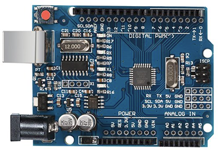
Figure 5. Low-cost Arduino Uno board selected for motor control
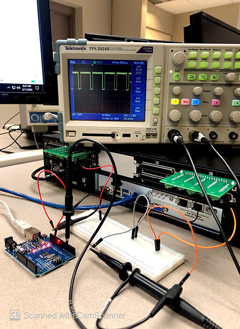
Figure 6. Arduino and OPAL-RT simulator setup