Interior Permanent Magnet Machine with Simplified Structure and Control for Harsh Environments
Professor Longya Xu – The Ohio State University
This research funded by the Grainger Center for Electric Machinery and Electromechanics aims to design and evaluate a new version of an interior permanent magnet (IPM) machine with a simplified electromagnetic structure and control hardware to enhance machine reliability. The IPM drive system is brushless, slot-less and sensor-less, as illustrated by the initial design in Figure 12.
Figure 12: Proposed brushless, slot-less and sensor-less IMP machine
The IPM stator laminations are a stack of iron rings that can be made inexpensively, and stator windings are simple copper bar groups that can be glued onto the inner wall of the stator core. The simplified magnetic structure of the IPM machine has a slot-less stator to facilitate the machine manufacturing process. The machine has a rotor with saliency, which identifies the rotor position at any instant, if the rotor is in motion or at standstill in harsh operating conditions. Thus, the rotor position is always available in starting and in rotation, without need for hardware sensors. The rotor position sensor, i.e., the optical encoder or resolver, is eliminated to enhance system reliability and save manufacturing and maintenance costs. With this brushless, slot-less and sensor-less design, it is expected that the IPM and control system will be easy to make, reliable to operate, and inexpensive to maintain.
The initial electromagnet design of the proposed IPM machine has been completed and its back EMF generation has been evaluated using finite element analysis. As expected, the back EMF is in a trapezoidal shape that increases machine power and torque density. To minimize torque ripple, a stepping vector control (SVC) algorithm is initiated and investigated by computer simulation. Comparison results for the conventional vector and SVC algorithms are shown in Figure 13. Note the results of torque ripple minimization.
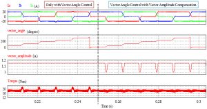
Figure 13: Current and torque in conventional vector and SVC operation
The sensorless control algorithm for the brushless dc (BLDC) IPM machine is investigated by both computer simulation and experimental testing. Experimental results for the rotor position detection algorithm that enables machine sensorless operation are shown in Figure 14 by phase currents (Ia, Ib, and Ic). In this algorithm, the detecting voltage pulses are injected to the related phases and corresponding current pulses are measured to determine the rotor position and commutation instant.
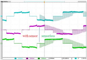
Figure 14: Phase currents (Ia, Ib, and Ic) in rotor sensor and sensorless controlled operation
Following are the results from our completed project:
1) Six-phase structure can provide a
3.6 percent increase in torque density.
2) Slot-less stator structure effectively
mitigates cogging torque.
3) The specially designed rotor provides
the largest back EMF and most bal-
anced flux density.
4) Stepping vector control minimizes
commutation torque ripple.
5) An optimal current angle control can
provide 5.4 percent more torque than a
conventional BLDC machine control.
6) Our sensorless control algorithm
achieves BLDC operation at zero and
any other speed.
In future work, we will explore the possibility of extending the proposed optimal current angle control to interior permanent magnet machines using reluctance torque. Application of the machine to electric vehicles will also be investigated.