Induction Machine Performance Improvements – Design-Oriented Approaches
Marco Amrhein with adviser Philip T. Krein
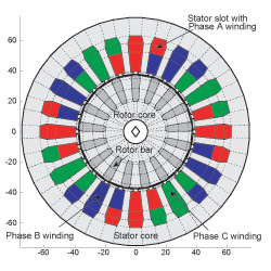
Figure 1 Cross-sectional view of the FEC motor and its magnetic circuit element distribution. The dotted lines represent the element boundaries.
New developments in power electronics technology, materials, and changing application requirements are driving advances in permanent-magnet and switched-reluctance machines. But special-purpose induction machines, due to of their low power density and low efficiency, are often not considered, particularly in the traction and aerospace community. Because induction machines need to satisfy the standards of the National Electrical Manufacturers Association, performance capabilities are limited. Computer-aided design (CAD) tools for special-purpose machines that overcome these limitations are not available.
Three different modeling approaches for CAD have been used in the past. Analytical machine models, the most common, have low computational effort and complexity but are inaccurate outside certain design restrictions. Finite element analysis (FEA), has, in principle, reasonable accuracy, but it requires massive computational effort in two-dimensional (2-D), and especially in three-dimensional (3-D) models, limiting its function to the detailed performance calculation of an already engineered machine. Magnetic equivalent circuits (MEC) provide a compromise between analytical models and FEA. They have reasonable accuracy combined with moderate computational effort, are flexible in size, and are easily parameterized and extended into 3-D models.
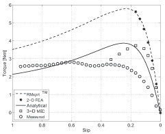
Figure 2 Comparison of the FEC motor steady-state torque characteristic.
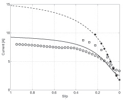
Figure 3 Comparison of the FEC motor steady-state stator phase currents.
The goal of this project is to further explore the feasibility of a general 3-D MEC modeling approach intended for design. The fundamental MEC theory needed to model electromechanical devices is addressed, including modeling of motion and force calculation based on the Maxwell Stress Tensor method. Further, automated generation of variable-sized magnetic circuit networks is investigated—a major concern in the application of MECs.
A 3-D MEC induction machine model that features arbitrary-sized magnetic networks is used to analyze the performance of a 500 W induction machine (FEC motor designed at the University of Illinois for the Future Energy Challenge competition). Its cross-sectional geometry is shown in Figure 1, including a magnetic circuit element distribution indicated by the dotted lines. This distribution already is more detailed than any current MEC model, considering leakage effects in more detail than other MEC models. Figures 2 and 3 compare the measured and simulated steady-state torque and stator phase current characteristics of the FEC motor. The simulation results comprise design software results (RMxprtTM), a 2-D FEA model, an analytical model whose parameters have been adjusted to match the measured current, and the 3-D MEC model. The FEC motor has design flaws; it saturates the stator and rotor teeth at nominal load, a fact not discovered by the design software and the associated FEA package (2-D FEA model). However, the 3-D MEC model estimates a limited torque capability and a smaller stator phase current due to a smaller air-gap flux. It is about an order of magnitude smaller in complexity and size than the FEA model, decreasing the computational effort needed to analyze the machine.
The 3-D MEC approach has been successfully applied to other devices such as an electromagnet and inductors. All the results indicate that MEC is a promising option for a design tool. Future work includes induction machine model improvements, model verification based on other machines, and implementation of the model into a CAD tool.