In-Lab Research Grid Generator Control of Hydro Resource and Pumped Hydro: Long-Term Energy Storage Systems
Professors Ted Brekken and Annette von Jouanne, Oregon State University Electrical Engineering and Computer Science, Wallace Energy Systems and Renewables Facility, Corvallis, Oregon
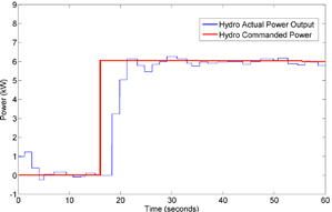
Figure 43: Hydro resource system response.
Grainger graduate student funding contributed to improving wind energy integration through more effective coordination of generation resources and energy storage
systems to buffer the variability of wind farm outputs. Work advanced on the established in-lab research grid, supported by a 480 V, 750 kVA dedicated utility supply. The in-lab grid features an emulated wind farm, energy
storage systems (supercapacitors, flow cell battery, and pumped hydro), traditional hydro generation resources, and local loads. The energy storage systems include a 25 kW, 50 kWh Zinc Bromine flow and a 25 kW, 90-second Maxwell supercapacitor system. The wind farm is emulated using an arbitrary waveform generator, which functions as a 120 kVA externally controlled source. An 80 hp wound rotor induction generation (WRIG) has been integrated to simulate the hydro and pumped hydro resource. Controls are in place to automatically spin up the WRIG, and synchronize to the in-lab grid system. Full control of real and reactive power is realized through a dSPACE rapid prototyping system.
The lab is controled by a dSPACE rapid-prototyping system, enabling researchers to create and test control algorithms in MATLAB and Simulink and rapidly implement them. Using this system and a stateof-the-art SEL751A feeder protection relay from Schweitzer Engineering, we are able to automatically spin up the WRIG, synchronize its three-phase waveform to our in-lab grid and automatically close the WRIG into the grid. A software state machine is used to perform the synchronization and closing of the WRIG. Real power is controlled through the torque command given to a four-quadrant adjustable speed drive and reactive power is controlled through the rotor voltage injected from a power supply under closed-loop control by dSPACE (see Figure 43). The pumped hydro resource emulates the Grand Coulee Dam with corresponding simulated energy storage capacity, efficiency, power output and response time. The pumped hydro system will receive commands based on hydro power output in the Bonneville Power Administration service area. Research was also initiated to investigate the pumped hydro role in resetting the energy storage system’s state of charge during off-peak hours. Finally, work on the energy controllers was advanced and detailed simulations have been completed to evaluate the performance of the energy storage controllers.
This research was supported by the Grainger Center for Electric Machinery and Electromechanics.