High-Speed, High Frequency Air-Core Machine and Drive
MS student Irin Jose with advisor K. Haran

Figure 6: 3-phase 750W inverter
This research developed a conventional hex bridge inverter to test the control algorithm developed for the 1 MW high-speed, high-frequency air-core machine drive for the NASA Fixed-Wing project. The 3-phase 220 V AC 750 W inverter which was designed and developed is shown in Figure 6.
The inverter board was successfully tested using a 3-phase resistive load with a sinusoidal PWM signal and a switching frequency of 5 kHz using a TI C2000 microcontroller. The 3-phase output line-to-line voltage and current waveform plot is shown in Figure 7.
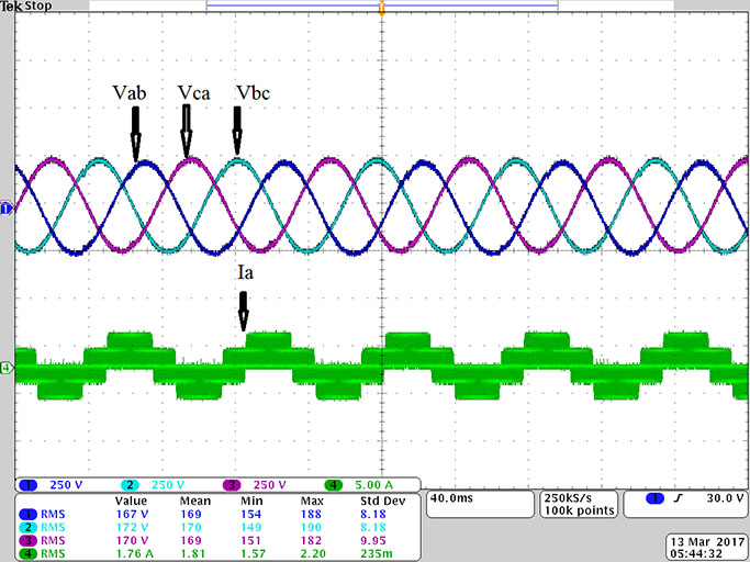
Figure 7: Line-to-line voltage and current waveform
In the next step, the gate signals will be provided from a field-programmable gate array (FPGA) module instead of a microcontroller, as the final motor drive system will have five different 200 kW inverters with gate signals from FPGA modules controlling the 1 MW motor. Two similar 750 W–FPGA modules controlled by a C2000 Delfino Master Controller will be used to test the PM motor available in the laboratory. This research was supported by NASA and the Grainger Center for Electric Machinery and Electromechanics.