Electric Machine Capability Characterization for Actuators of Disaster Response Robots
CEME Collaborator Professor Julia Zhang – Oregon State University
The objective of this project, funded by the Grainger Center for Electric Machinery and Electromechanics, is to understand the torque-speed requirements of electric machines used as actuators for disaster response robots so these robots can accurately and safely accomplish search and rescue tasks. A humanoid robot model including the hips, thighs, shanks, and feet, shown in Figure 15, has been built using the Matlab/SimMechanics toolbox to simulate two motions: walking and climbing stairs.
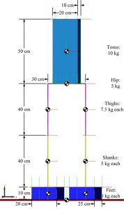
Figure 15: Robot model in Matlab/SimMechanics inluding hips, thighs, shank, and feet
The simulation includes four basic steps: (1) physical design, (2) gait synthesis, (3) dynamic modeling and (4) actuator control. The physical-design phase defines the robot parameters, including the dimension, weight and material of each component. Gait synthesis generates the command motion trajectories for robot joints to be converted to the control commands for the robot joint actuators. Dynamic stability analysis determines the robot system equilibrium using zero-moment point criteria. By controlling the actuators, the system uses the Euler-Lagrange approach to calculate electromagnetic torque for actuating the joints.
Biomechanics and mechanical engineering were used to determine several set points on the ankle trajectories. Figure 16 shows the ankle trajectories over five footsteps generated by using the cubic Hermite interpolation method based on these set points. Although it is theoretically possible to generate an infinite number of trajectories, it is crucial to generate those that can guarantee robot dynamic stability. The zero-moment point method was applied to evaluate robot dynamic stability when it is in motion for various
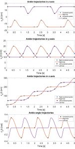
Figure 16: Ankle trajectories in x-axis (displacement that is perpendicular to the walking direction in the horizontal plane), y-axis (displacement in the vertical level), z-axis (distance in the walking direction), and angle between the foot and the ground in five footsteps of walking on a smooth terrain generated by piecewise cubic hermite interpolation polynomial
trajectories, and the best trajectory set was chosen to command the actuators. Figure 17 shows the simulation results of the operating torque-speed trajectories for the two-degree-of-freedom ankle joint actuators using the trajectories in Figure 16. Since the walking motions are symmetric in the xy-plane, the torque-speed requirements are also symmetric. Similarly, the walking motions of both legs are the same in the yz-plane. Torque-speed requirements for both legs are similar.
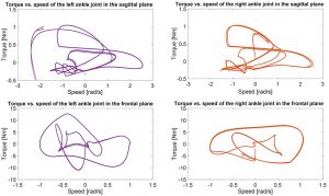
Figure 17: Operating torque-speed requirements in the ankle joint actua-tors in the sagittal plane (rotating along x-axis) and frontal plane (rotating along z-axis) with the selected trajectories in Figure 16