Direct-Drive Rotary Generator for Ocean Wave Energy Application
Christopher Haller and Hai Yue Han with advisers Ted Brekken and Annette von Jouanne, Oregon State University
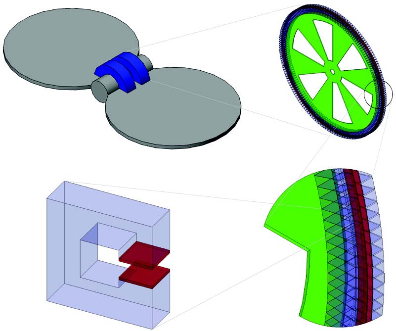
Figure 5: Buoy generator mechanical drawing.
The world’s oceans are emerging as a dense new source of renewable energy through the use of wave generators. Ocean-wave driven generators pose design challenges which are caused by long wave periods and varying wave profi les. The goal of this research project is to design a permanent-magnet alternating-current generator sized for utility purposes. To maintain serviceability and cost effectiveness, the size will be limited to a range below one megawatt (200 kW to 400 kW ), and to allow for scalable power generation into the megawatt range, the generator can be deployed to the ocean as part of a localized set of matched generators. The generator will be designed as a direct-drive unit which eliminates the possibility of gearbox failure. With power of P ∝ ω2rl, and a low rotational speed (ω) of 0.5 rad/s dictated by long wave periods (commonly seen on the Western U.S. seaboard), either a large machine radius (r), or a long machine (l) is necessary to achieve the target power level. A practical machine radius limit of 3.5 m was chosen, which then allows length (l) to be scaled with machine capacity.
The machine design chosen is shown in Figure 5. It consists of two large fl oating plates with a common central hinge point. The middle point of the hinge is anchored to the sea fl oor so that it will remain stationary, while the fl oating plates attached to it are allowed to rotate up and down as they are acted upon by passing waves. A rotary generator is then placed inside this central hinge point, which uses the floating plates as moving torque arms, and the anchored center of the hinge as a stationary point. The generator itself is composed of iron C-cores with two magnets mounted just inside the ends of each C-core. The C-core, from which the magnetic circuit of the machine was derived, is shown in the bottom left corner of Figure 5.
To optimize machine efficiency, a MATLAB-implemented genetic algorithm (GA) and cost function were employed. The following process was used. A large array of motor “chromosomes” called a “population” is created. Each chromosome in the population is composed of motor “genes.” These are: number of machine layers, total length of C-core, air gap length, magnet cross-sectional area, magnet length, magnet thickness, wire turn quantity, and wire gauge. The GA takes this population of chromosomes and evaluates the mechanical and electrical validity of each, determining a “fi tness” for each motor chromosome. The chromosome’s fi tness is based benefi cially on the power production and motor efficiency, and negatively on machine mass, wire size, and number of wire turns.
The population of motors is then sorted, and the population half with lower rated fi tness levels is discarded. The better half of the population then “asexually” reproduces, which essentially copies the good half of the population into the discarded population’s old locations. Once the population has been regenerated to full capacity, this new population is either crossed (exchanges genes between chromosomes), mutated (genes are randomly modifi ed), or both. This creates a fresh new population of motor chromosomes which then repeat the fi tness evaluation process.
Preliminary results obtained from the GA using the motor model of Figure 5 have created a motor of 20 machine layers, a C-core length of 0.375 m (per side), an air gap length of 0.0795 m, magnet cross-sectional area of 0.001 m2, magnet length of 0.1865m, magnet thickness of 0.1465 m, 16 wire turns, and an AWG wire size of 16. These results give a machine with 372 kW total power output, 33009 kg weight, and 94% efficiency. The results are not yet fi nalized; optimizations are needed to reduce total machine mass, and the magnetic circuit in Ansoft’s Maxwell (an FEA tool) must be fine-tuned. Work is expected to be completed by the end of September.
This research is funded by the Grainger Center for Electric Machinery and Electromechanics.