Behavioral Analysis of Various IGBT Structures under Hard and Soft Overcurrent Turn-off
Abhishek Banerjee with adviser P. T. Krein
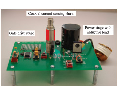
Figure 20 Hardware set-up with IGBT under test.
Protection of insulated gate bipolar transistors (IGBTs, which are used in high-voltage inverters for automotive and industrial motor-drive applications) from overcurrent and short-circuit current during operation is essential to ensure system reliability. Faults in electric machine drives result in the IGBTs carrying a current substantially higher than rated (often tens of times during short-circuit current). This may result in device rupture from any of the following:
- Thermal dissipation: The higher current causes the junction temperature of the device to rise in a very short time owing to its fast thermal time constant.
- Latching: The intrinsic p-n-p-n thyristor in the IGBT can latch at higher current, resulting first in loss of device gate-control and then rupture.
- Over-voltage: Turn-off of IGBTs at higher currents can cause voltage overshoot due to parasitic inductances. If the overshoot exceeds the breakdown voltage, it can cause silicon damage.
Figure 21 Logic level gate pulse is still on (green) while fault is detected. Current is limited (magenta) and gate undergoes two-level turn-off (yellow). Overshoot is also seen (blue).
This project analyzes overcurrent and short-circuit behavior of 600 V/30 A IGBTs made by International Rectifier® and Infineon Technologies®. A behavioral comparison is carried out between the devices during hard and soft shut-down following overcurrent detection.
The protection scheme, where the collector-emitter voltage is monitored, is known as “desaturation detection.” Sudden unexpected high currents force the voltage across the device to rise when it is supposed to be low during on-state. The rise is detected and, consequently, the protection circuitry is initiated, bringing down the gate voltage to reduce the collector-emitter current, and in some cases, shutting down the device altogether. Shut-down can be regular (hard) or soft, where the timing is controlled by external capacitors and Zener diodes. Again, depending on the application, soft shut-down may not be necessary. The response of different IGBT structures to hard and soft turn-off will also be analyzed.
Hardware has been setup as shown in Figure 20. The power stage consists of a half-bridge configuration where the upper IGBT is shorted to behave as a free-wheeling diode and the lower is under test. A sample test result is shown in Figure 21 with the soft turn-off initiated and the IGBT shut-off even before the logic-level gate signal turns off.