Automated System Identification and Controller Tuning for Digitally-controlled DC-DC Converters
Ali Davoudi with advisor P. L. Chapman
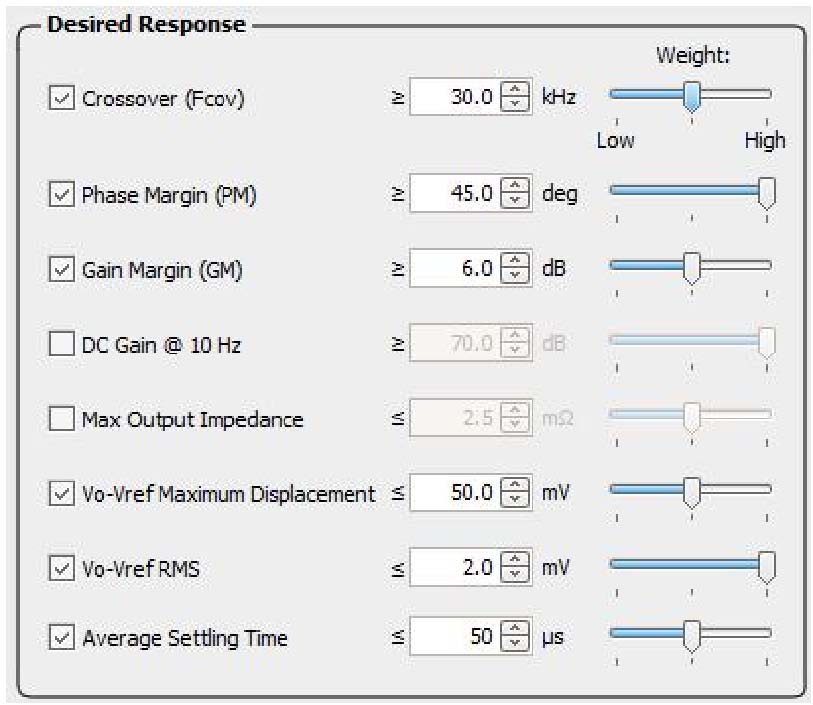
Figure 19: Proposed auto-tuning configuration.
Interleaved multi-phase dc-dc converters are widely used in microprocessor power supplies that require tight voltage regulation in the presence of extreme load transients. The voltage regulator modules are conventionally facilitated as multi-phase dc-dc buck converters. Analog controllers have been successfully implemented in the multi-phase buck converters, however, digital controllers provide less susceptibility to noise and parameter variations, low power consumption, passive component elimination, system diagnostic capability, and programmability.The
controller design process and small-signal frequency-domain characterization require system identification. System identification in situ can benefit from the digital nature of the feedback signal between the converter and a processing unit. Once the converter system and parameters are identified, the digital controller has to be designed. Design limitations and desired dynamic behaviors complicate the controller design process and necessitate automated tuning of the controller. Therefore, a computer-generated auto-tuning framework is set forth that provides the required digital controller coefficients to meet desired time and frequency performance criteria.
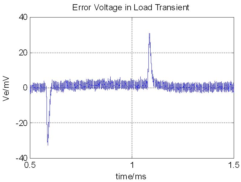
Figure 20: Measured output voltage error of a dual-phase buck converter under study.
First, conventional identification and tuning techniques are integrated with the controller. These have shown valid results and mainly monitor crossover frequency and phase margin. However, to effectively mitigate load transients, more design criteria may be needed. In addition, the desired dynamic performance imposes certain limitations on small-signal frequency-domain characteristics and/or large-signal time-domain transients. These limitations can be set using user input and/or by load specifications. Using several time- and frequency-domain simulations, a cost function is formulated and optimized offline to yield controller coefficients. Once these coefficients are determined, they are loaded in the controller. The identification and tuning results are then verified using a dual-stage buck converter. Here, the auto-tuning metrics chosen in Figure 19 are used to impose a desired dynamic response. The output voltage of the dual-phase converter (shown in Figure 20), despite an 800% change in load demand, follows the dynamic response imposed by the metric in Figure 19.
This research was funded by the Grainger Center for Electric Machinery and Electromechanics.