Ac Loss Measurement Test Bench for Measuring ac Losses in Superconducting Cables Under Transverse Rotating Magnetic Field (20-K, ¬1-T, 0–150 Hz)
Thanatheepan Balachandran with adviser K. Haran
Ac losses in superconducting (SC) wires can be measured through electromagnetic methods, the heater-based calorimetric method, or the cryogen boil-off-rate-based calorimetric method. Losses must be measured in the transverse rotating field to validate the loss estimation in electrical machines. A rotating electrical field inside a cryogenic environment can be created with a permanent magnet (PM) rotor, by specially arranging alternating field coils, or by rotating a sample in a uniform field. Each of the measurement methods available in the literature has its own limitations at the applied field level, frequency, and achievable sample temperature. Figure 1 shows the comparison of available ac-loss measurement test benches to UIUC ac-loss measurement capability. Fully SC electric propulsion machines operate at the 0.4–0.7 Tesla (T) air-gap field range, and higher electrical frequencies in the range of 100–300 Hz. Wind turbines operate at the 0.5–1 T air-gap field range and at low frequencies less than one Hz. There are no measured loss data available for Magnesium diboride (MgB2) conductors in these electrical-machine application spaces.
This research focuses on experimentally validating the ac losses in MgB2 wires for electric propulsion and wind turbine applications. Figure 2 shows the ac loss measurement setup. A two-pole rare-earth PM rotor is used create a high magnetic field around one 1-T inside a 40-mm air gap. MgB2 wire samples are attached to a ceramic sample holder to avoid eddy-current losses in the holder. The holder is attached to the cold head to maintain it at the required temperature while placing the samples inside the rotor air gap. The PM rotor and samples are placed inside a stationary ultra-low vacuum chamber to avoid convection losses. The PM rotor is rotated using a ferrofluid rotary coupler to apply the rotating field. The field frequency is varied by varying the rotating speed of the rotor.
The heater-based calorimetric method is used to measure the ac losses. The cryocooler is operated in constant power mode. A heater is attached to the sample to control the heat load on the cryocooler and the cold-head temperature. A temperature controller is used to control the heater to maintain that temperature. At stable condition and idle operation, no losses are generated in the wire, and the heat load on the cryocooler will be equal to the heat load applied to the heater and the system thermal losses. When the rotating field is applied, the cold-head temperature will be increased due to the presence of additional ac losses. A constant temperature can be maintained by reducing the heat dissipated in the heater. The reduction in the heat load can be measured to estimate the ac losses generated in the sample. Figure 3 shows the low-frequency measurement measured in the ac-loss test bench.
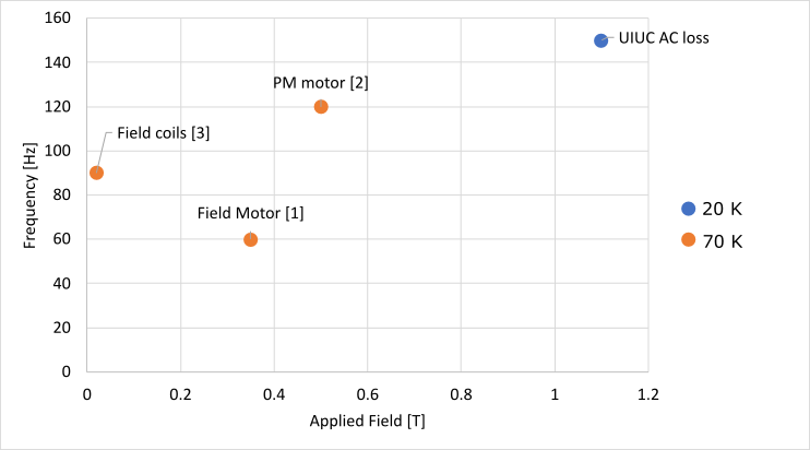
Figure 1: Ac-loss measurement test-bench comparison
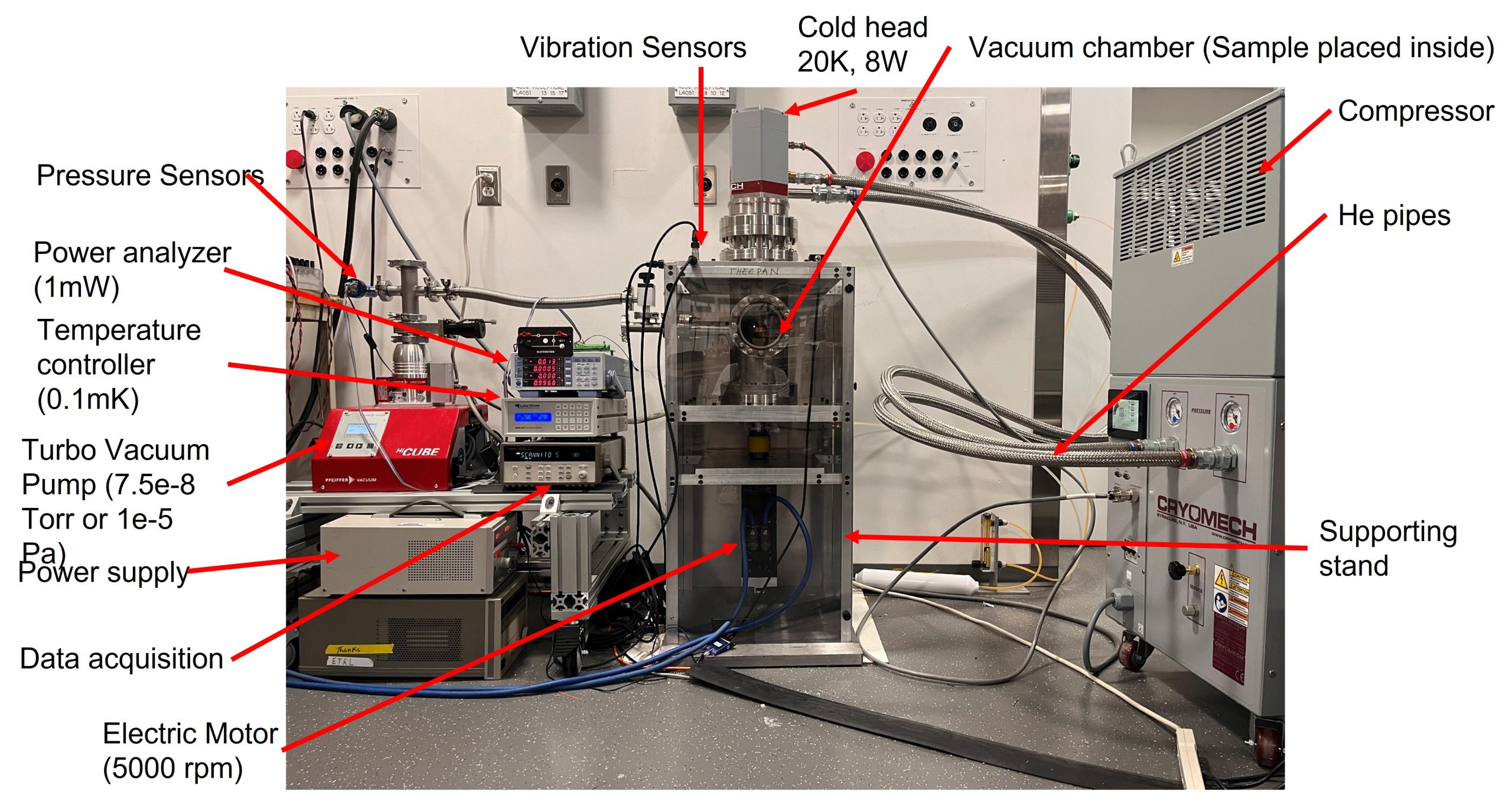
Figure 2: Ac-loss measurement test bench
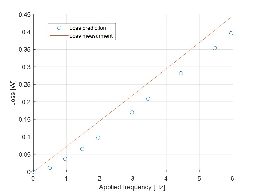
Figure 3: Loss measurement on a 3.2-m wire sample