A Transfer Function Approach to Active Damping of an Induction Motor Drive
PhD student Srikanthan Sridharan with advisor P. T. Krein
The use of LC filters between inverter and motor terminals results in undesirable resonant oscillations in motor voltages and currents. Passive damping methods employing physical resistors to suppress these oscillations contribute to additional losses. So, loss-less active damping methods with virtual resistors have been explored as a viable alternative. In a typical active damping implementation, current flow in the virtual resistor across the filter capacitor is emulated in the control loop using motor voltage feedback. Conventionally, the virtual resistance value is fixed based on empirical rules and left unchanged for all operating conditions. Choosing the resistance value is important, because high values may provide insufficient damping, whereas low values can lead to excessive damping and cause a degraded dynamic response. A small-signal transfer function-based approach is developed in this research to select a resistance value which can be dynamically varied, based on operating conditions. The control scheme, implemented in a d-q frame, provides the flexibility of using a differential damping approach, where the d and q axis resistance values need not be equal. Simulation and experimental results confirm the effectiveness of active damping in mitigating resonance effects. This adds new degrees of freedom to output filter design. Effective suppression of resonant oscillations in stator voltages and currents can be seen in Figures 3(a) and (b), when the active damping controller is activated at 0.25 s. This research is supported by the Grainger Center for Electric Machinery and Electromechanics.
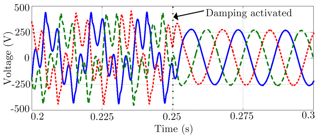

Figure 3: Before and after damping at 0.25 s: (a) three-phase stator voltages and –(b) three-phase stator currents