Inverter Characterization for Intermittent and Peak Duty Motor Drives
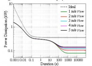
Figure 4: Time ratings estimates for a three-phase, IGBT inverter
Veysel (Tutku) Buyukdegirmenci with adviser P. T. Krein
Dynamic electro-thermal inverter and power switch models have been extensively studied in the past, but inverter and drive short-term thermal and electrical capabilities have not been investigated. This research examines inverter short-time ratings, electrical limitations and proper sizing under peak duty applications. Previous electro-thermal models rely on proprietary dimensional data; thus for a generic investigation, transient thermal characteristics are used. A well-established inverter transient thermal model that relies only on manufacturer data is developed. Using this model, maximum allowable output current and associated time ratings are obtained for the maximum temperature rise. The inverter model is experimentally validated using a three-phase IGBT inverter.
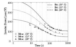
Figure 5: Experimental results compared to simulated estimates of time ratings for 10°C, 15°C and 20°C temperature rise
Maximum allowable inverter heat dissipation for different cooling rates is shown in Fig. 4. The dashed curve displays the thermal capability of an inverter with ideal cooling. Although this operation is not actually attainable, it demonstrates the upper bound on short-time capabilities decoupled from cooling performance. Including realistic cooling mechanisms with finite heat capacity, time ratings shown in Fig. 4 can be separated into two distinct time scales. The first region corresponds to the first few seconds with the heat dissipation capability decoupled from cooling. The limit here stems from the semiconductor thermal mass. Even with ideal cooling, the power dissipation in Region 1 is limited by semiconductor ratings. The second region corresponds to steady-state limits and is affected by cooling performance. The time-scale separation between these two regions is due to finite heat sink or cold plate thermal mass. Experimental results, provided in Fig. 5 for temperature rises of 10°C, 15°C riseand 20°C, behave similarly to the simulated characteristics and show that in a carefully rated drive system, the output limitation is related to inverter thermal behavior. Inverter time ratings can be improved through a careful choice of heat sink or cold plate heat capacity.
This research is supported by the Grainger Center for Electric Machinery and Electromechanics.