Voltage Regulator Module for Loads with Fast Transients: Predictive Energy Optimization and More
Yingying Kuai with advisor P. L. Chapman
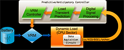
Figure 29: Block diagram of the VRM scheme.
State-of-the-art voltage regulator modules (VRM) need to supply 1.5 V at 125 A and maintain the output voltage within 75 mV overshoot during load transients with slew-rates up to 50A/μs. To achieve such strict voltage regulation without increasing output capacitance, predictive control (also referred to as anticipatory control) has been proposed. In the proposed control scheme, future load transients are predicted and then a warning signal is made available to the VRM before the transient actually occurs. The VRM controller could take advantage of this signal to greatly improve VRM transient response. A block diagram of this scheme is shown in Figure 29.
To predict future load transients, digital signals that could both sense the load current and correlate to load dynamics need to be acquired. An example of such signals is the voltage identification signal of a CPU. Frequency
selection signals could also provide information on load current. An Intel-based desktop PC motherboard was chosen as the subject of study. Experiments are to be performed to decide the feasibility of such measurements, and to establish empirical groundwork for the project.
Once the sensing and storage of desired data is made available, VRM controller improvement will be realized through two steps. First, a comprehensive study of various data processing methods will be performed. The goal is to develop an efficient and accurate algorithm such that useful information for transient prediction could be extracted. Modern digital signal processing techniques, including windowing, filtering, and spectrum analysis, are candidates for this purpose. Second, the existence of the correlation between future load transients and the extracted information will be confirmed. Even if the conclusion at this stage turns out to be negative, this study still provides valuable input for future work.
When future current transient prediction is successful and the warning signal is made available for the VRM controller, enhancement of transient response could then be realized through various ways. A MOSFET could be controlled as a ballast load to the system, in addition to the CPU, to serve as a temporary energy dissipation device. In addition, the controller could switch the VRM operation between two or several modes to optimize efficiency and response. Novel control schemes, such as new hysteretic control, could also be proposed for the predictive control system to offer optimum performance.
This work is supported by the Grainger Center for Electric Machinery and Electromechanics and National Science Foundation grant ECS 06-21643.