Reduction of Dynamic Nonlinear Models of Magnetic Devices
Liyan Qu with adviser Patrick L. Chapman
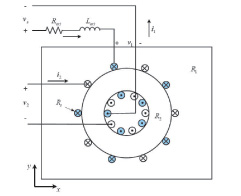
Figure 39 Example transformer for model development.
FEM is a powerful numerical technique widely used in the analysis of electric machinery and power electronics. Given geometrical data and material information, physics-based, FEA models can be generated automatically. Unlike behavioral modals, they sometimes rely on many unrealistic assumptions (such as sinusoidal windings, perfectly balanced windings, and absence of hysteresis), and are constructed by analytical methods. However, FEA models typically have thousands of state variables even though the underlying physical device can be accurately modeled with only a few states. Even a linear time invariant system derived from this type of approximation requires vast computer resources and is highly numerically intense and awkward to integrate into system-level models due to the large number of state variables included. It has been shown that FEM-based, high-order models can be mathematically reduced in order by using order-reduction techniques with quantifiable error bounds. Such model order reduction (MOR) methods have been used extensively in various fields of science and engineering. Ideally, once a reduction algorithm is developed, it is generalized and coded so the mathematical complexity is transparent to the end user. As such, a physical description of the device can be converted to a useful, low-order, rapidly-simulating model while preserving the underlying physical meaning.
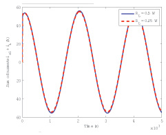
Figure 40 The sum of the two winding currents with two different load combination
Automatic extraction of low-order, dynamic models for nonlinear magnetic devices with consideration of saturation and hysteresis has been studied in our previous work. This work is extended to multiwinding cases. The use of an equivalent current significantly simplifies the MOR procedure in the proposed method. Figure 39 shows an example transformer for model development. The two winding systems (the primary one is blue, the secondary white) are intersecting. Since the total magnetic field is induced by both winding currents, the sum of them can be used as an equivalent current, which generates a magnetic field that is the same as the total magnetic field induced by both windings currents. The use of an equivalent current significantly simplifies the MOR procedure in the proposed method. Simulation results of the sum of the two winding currents are shown in Figure 40 under different load combinations. During the simulation with the reduced-order models, the use of an equivalent circuit provides an easy way to select the suitable extracted models. The equivalent current is obtained at each time step. Then, the constructed linearized systems, based on the equivalent currents of similar values, will be selected to approximate the original system for the next time step.