Parasitic Parameters Simulation and Measurement for Electric Machine Windings
CEME Collaborator Professor Julia Zhang and Yanyan Xie – The Ohio State University
This project is jointly funded by the Grainger Center for Electric Machinery and Electromechanics (CEME) and Ford Motor Company. The objective is to understand how to calculate and measure the parasitic parameters of electric machine windings in order to model the voltage stress of every conductor. We hope to reduce/prevent premature machine winding insulation failures caused by fast-switching power electronic inverters.
Both finite element (FE) simulation and experimental approaches are used. In FE simulations, 2D models are built to include a stator, individual conductors for stator windings. Various combinations of wire positions are tested. Figure 1 shows 2 of many combinations of wire positions tested and the test setup to replicate the wire configuration in simulations. Each conductor is represented by numbering ij, where i means the ith turn and j means the jth parallel branch of one turn. This model has 4 turns in series and 4 parallel branches for each turn. The conductors of the same color represent the parallel branches in the same turn. The electrostatic solver in the FE tool is used to calculate the self-capacitances and mutual-capacitances of wires. The self-capacitance is defined as the capacitance between a wire and the stator ground wall. The mutual-capacitance is defined as the capacitance between any of two wires. A network analyzer was used to measure all self-capacitances and mutual capacitances. The capacitance values from simulations and those from experimental tests were compared and show a good consistency with an error below 10%, if the lengths of the end wires could be shortened as much as possible. Figure 2 shows a complicated random-wound winding with 6 turns in series and 16 parallel wires for each turn. Three digits are used to identify each conductor. The first digit represents the conductor turn number. The last two digits identify the parallel wires (1 through 16). The self-capacitances and the mutual capacitances between Conductor 508 and the other conductors are plotted. The color represents the range of the capacitance values. Conductors near the stator ground wall have high self-capacitances. Conductors closer to Conductor 508 have higher mutual capacitances. Capacitance measurements are undergoing.
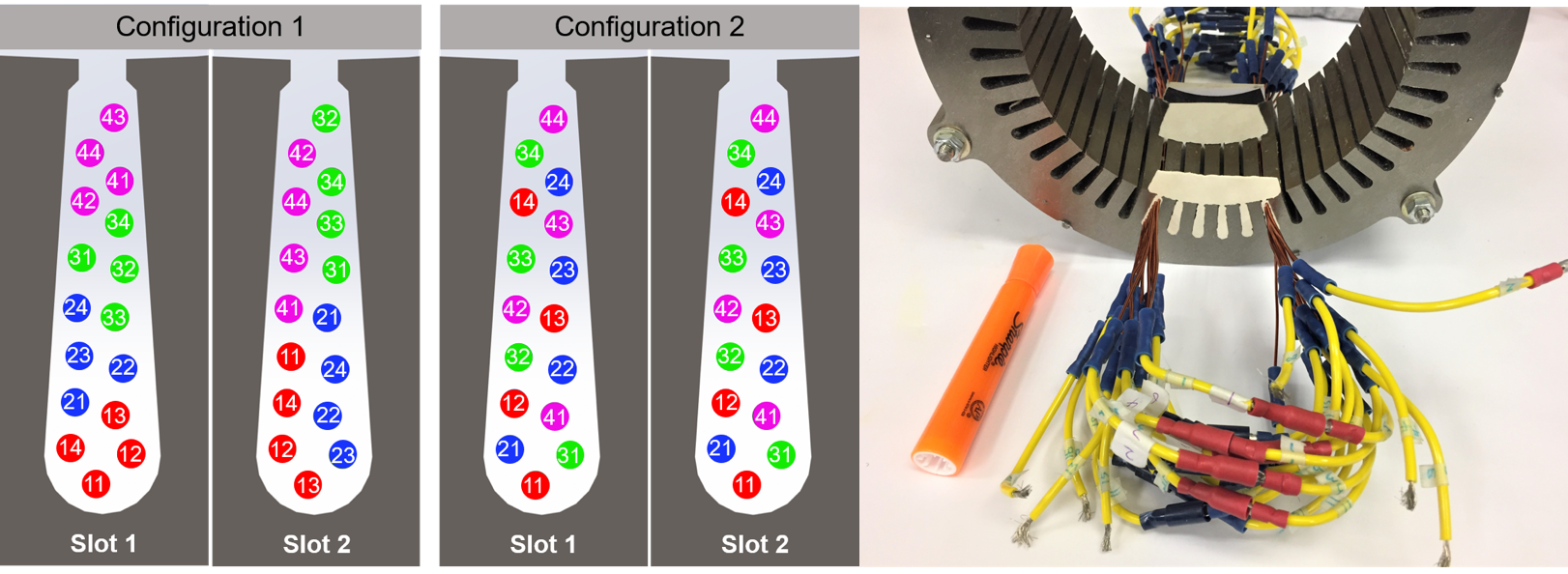
Figure 1: Two combinations of wire positions tested and test setup to replicate the wire configurations in simulations
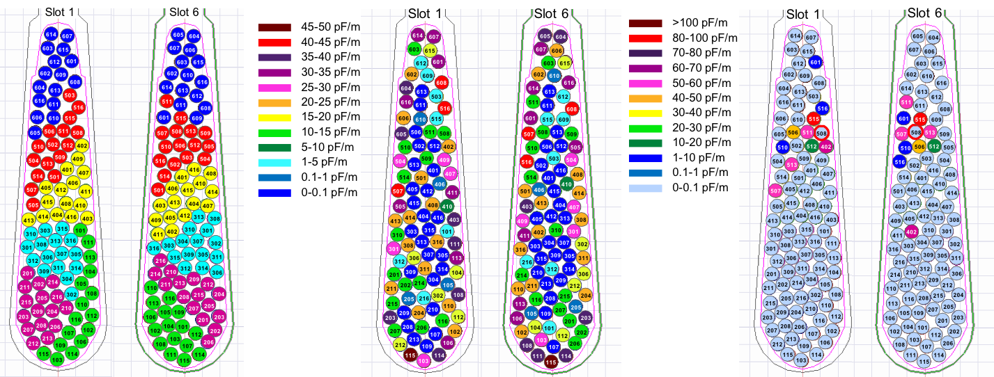
Figure 2: Random-wound winding with 6 turns in series and 16 parallel wires for each turn