Magnetic Equivalent Circuits Applied to Induction Machine Design
Marco Amrhein with adviser Philip T. Krein
The design of induction machines has traditionally been done with analytical models, which usually consist of an electrical equivalent circuit approximation of the machines. These models are enhanced with empirical equations that were based on measurement results in order to include various effects. Machine designers use these models to analyze and optimize the performance of new machine designs. However, in order to successfully design a machine, most designers need to rely on their own experience or on the expert knowledge available in industry and literature. Computer-aided design tools have been adopted for iterative design processes. However, even nowadays these processes are almost exclusively based on analytical machine models. The introduction of finite element analysis (FEA) (early 1970s) to the analysis and synthesis of electric machines did not change the design procedure. Finite elements are not part of the actual design process; they merely verify a finished machine design. There are multiple reasons for the lack of direct integration of FEA into an optimization process. FEA is computationally very expensive, because a time-domain solution is required to get a satisfactory analysis of the machine. In addition, it is difficult to relate the FEA results, obtained in a geometry- and time-based domain, to traditional results of the analytical models (circuit-domain).
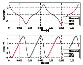
Figure 1: Simulated vs. measured steady-state coil current and voltage for 3C90 U-core inductor, 40 turns.
A third method of analyzing electrical machines is based on magnetic equivalent circuits (MECs). Similar to electric circuits, MECs use magnetic circuit components to model the flow of flux in a given geometry. Because the magnetic structure of an electric machine is generally simple, MECs have been applied to model machines—in particular 13 induction machines—with simple MECs yielding satisfactory results. MECs are computationally less expensive than FEA, because the number of circuit components required is smaller than the number of elements. However, designers have not yet used MEC in their optimization tools because it is difficult to automate the reluctance network generation (compared to meshing in FEA), and torque and loss calculations have not been thoroughly researched.
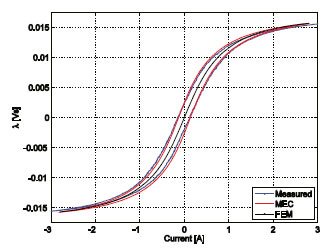
Figure 2: Simulated vs. measured hysteresis characteristics for 3C90 U-core inductor, 40 turns.
The goal of this project is to further investigate the feasibility of MEC for use as an induction machines design tool. In particular, a machine model will be programmed that lends itself to the use of an iterative optimization process. Also, the MEC model will be compared to the performance of currently available FEA tools. So far, MEC has been applied to the analysis of various inductor geometries in order to verify the proper function of the method. In Figure 1 the measured and simulated current and power loss waveforms of a Ucore inductor are shown. Figure 2 shows the relationship between flux linkage and current for the same inductor core. Note that in Figure 2, the hysteresis of the magnetic material has been modeled within MEC, something that is neglected in almost all analysis tools (such as FEA). Thus, the power loss as well as the flux linkage-current relationship can be modeled more accurately. In general, the results obtained with the MEC code agree very well with the measurements.
Further work includes the actual programming of the induction machine model into the existing MEC code. This includes the implementation of rotor rotation and torque calculation as well as the programming of a reluctance network generator based on a set of input parameters. The model then needs to be verified, in particular the torque calculation. Also, the MEC approach will be tested against machines operated at extreme conditions, which usually yield simulation results that do not agree with actual measurements.