Induction Motor Drive Design Based on Drive-Cycle Energy Minimization
MS student Xuan Yi with advisor K. Haran
The goal of this high-speed electrical machine project funded by NASA and the Grainger Center for Electric Machinery and Electromechanics is to build a permanent magnet machine with 13 KW/kg (8hp/lb) power density and over 96% efficiency under rated conditions. The targeted power density (twice or three times larger than is common in electrical machines) is achieved by utilizing a high-frequency air-core armature in intimate contact with heat fins within the self-contained machine bore. The fins will be cooled with high-velocity forced air pumped by vanes on the rotor end plates. Such a high-power density, high-speed electrical machine involves a tremendous amount of heat, windage loss, and iron loss. To make sure it operates in a safe temperature range requires effective thermal management to direct the heat loss outside the ma-
chine. Figure 11 shows a heat transfer analysis using Flux (finite element analysis [FEA] software) to simulate the 2-D conduction mode. ANSYS (FEA and computational fluid dynamics) is used to estimate temperature distribution in the 3-D model shown in Figure 12. Currently, most thermal studies, such as copper-winding temperature and permanent-magnet temperature, are implemented in a 2-D conduction model. For future work, the complete 3-D temperature distribution estimation for the whole motor coupled with air flows is expected.
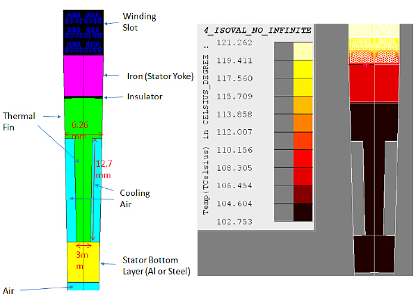
Figure 11: Heat transfer analysis to simulate 2-D conduction mode
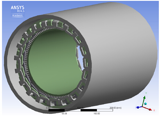
Figure 12: Temperature distribution in the 3-D model