Dynamic Simulation of Dual Mechanical Port Machine
Yuan Zhang with adviser L. Xu, The Ohio State University

Figure 10 DMP machine structure.
The dual mechanical port (DMP) machine shown in Figure 10 has more than one mechanical port—the outer phase modulation (PM) rotor and the inner wound rotor. The PM rotor is sandwiched by the stator and inner wound rotor. The black parts of PM rotor represent north poles and the red parts south poles. Meanwhile, both the stator and the inner wound rotor are excited (windings are not shown in Figure 10). This machine is promising in many applications such as multisource hybrid traction, integrated starter and generator, variable gearboxes and so forth. In the dynamic simulation presented in this report, we concentrate on its application in hybridelectric vehicles.
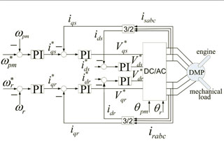
Figure 11 Control block diagram.
We have already established the dynamic model for the DMP machine, designed a 125- kW prototype, and examined the torque capability and magnetic field distribution by using finite element analysis (FEM). In this report, much attention is given to the DMP machine system dynamics. Specifically, we have simulated the whole process of a hybrid-electrical vehicle from starting to coming to a stop. The significant feature of the DMP machine is its dual mechanical input/output ports (shafts), which makes the operation modes of the machine versatile.

Figure 12 Simulation results of DMP power balance.
The overall system is configured as shown in Figure 11 with 2-speed closedloop and 4-current closed-loop control. To highlight the DMP uniqueness in operation, the entire simulation process is divided into 6 major intervals, corresponding to PM-rotor acceleration, wound-rotor acceleration, engine starting, high-speed acceleration and deceleration, engine stop and vehicle stop.
The DMP system power balance is shown in Figure 12. The simulated current and power confirm the analysis stated above.