Distributed Frequency Control of Inertia-Less AC Microgrids
Distributed Frequency Control of Inertia-Less AC Microgrids
PhD student Stanton T. Cady with adviser A. Domínguez-García
The focus of this work is to develop and simulate a microgrid control architecture designed to ensure stable and synchronized operation at a specific frequency. Compared with previous work in which we designed and experimentally validated an approach to distributed frequency regulation, we analytically show that our new architecture results in stable and synchronized operation while eliminating frequency error that results from load changes. Whereas our earlier approach relied on the presence of at least one synchronous generator, our new architecture is designed to work in microgrids with no inertia, those, for example, comprising entirely inverter-interfaced generation resources with no spinning mass.
To regulate frequency while ensuring stable and synchronized operation, our controller utilizes a two-step approach. The first step allows the generators to compute set-points that result in phase- cohesive operation given the current load; the second executes over several rounds to eliminate any frequency error that arises due to load perturbations. Both steps combine computations performed by local controllers present at each load and generation bus with information exchanged among neighboring buses. Together, these distributed calculations allow the generator nodes to obtain global information with which they can make local decisions that collectively drive the system to a desired state, i.e., one in which the frequency error is zero.
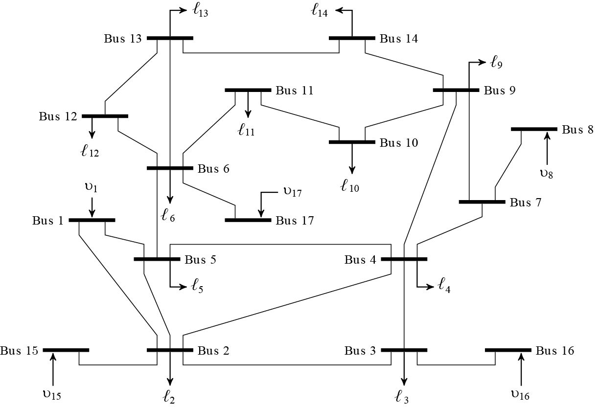
Figure 1: One-line diagram of 17-bus test system
To demonstrate our proposed two-step control architecture, we numerically simulated the 17-bus network shown in Figure 1. This system is based on the IEEE 14-bus test case, modified so that each bus has either a generator or a load attached, but not both. At the beginning of the simulation, the first step of the control scheme adjusts the generator set-points so as to guarantee stability and synchronism. This adjustment can be seen in Figure 2 during the time between t=0 and t=0.75 seconds. At t=1s and t=6s, the loads at buses 9 and 5 are increased by 70% and 75%, respectively. As Figure 2 shows, these perturbations result in a nonzero frequency error (characterized by the fact that the derivative of the voltage angles is nonzero), but that error is quickly eliminated by the second step of our proposed architecture. This work is funded by the National Science Foundation under grant ECCS-CPS-1135598

Figure 2: Evolution of bus voltage angles following two load perturbations