Distributed Control Architecture for Microgrids
Samuel Utomi with Advisor Prof. Alejandro Dominguez Garcia
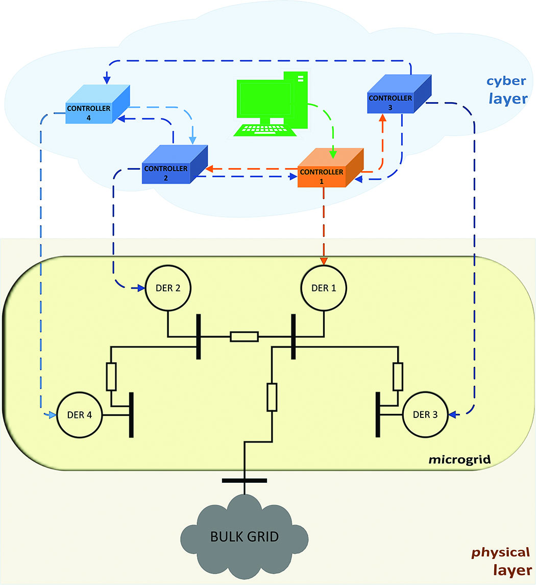
Figure 34: Distribution control architecture testbed
There has been a proliferation of distributed energy resources (DERs) due to their reduced cost and the desire to increase grid infrastructure reliability and stability. This has led to the viable integration of decentralized generation and the need to find innovative control strategies to obtain optimal performance. While in large power systems generation control functions are centralized, integrating decentralized generation requires distributed control strategies, i.e., the generator makes control decisions using local information.
Our research focuses on development and implementation of this distributed control architecture in order to provide frequency regulation services to the bulk grid, while ensuring optimal dispatch of these DERs. With a group of DERs, collectively known as a microgrid, the goal is to use distributed control strategies to gain a system objective while keeping generator set points within limits. This is achieved by employing iterative algorithms that combine local measurements and certain information from neighboring generating units with local, low-complexity computations.
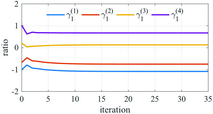
Figure 35: Evolution of consensus results of node 1 in first step
Figure 34 shows our testbed setup. Arduino Mega microprocessor controllers communicate wirelessly by using an XBee shield attached to each one. The lead controller receives a frequency regulation signal from the computer which it then distributes to the other controllers. Once the algorithm is complete, controllers send the resulting reference signal to the hardware-in-the-loop (HIL) simulator. It contains a model of our microgrid that provides a set amount of power to the bulk grid, based on the regulation signal.
Modifications to the original algorithm were made to implement an optimal DER coordination problem where the dispatching objective is to minimize the total incremental distribution
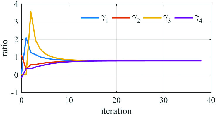
Figure 36: Evolution of consensus results for all nodes in final step
network losses while delivering the requested amount of active power at the interconnection bus. This is a two-step process. Figure 35 highlights the evolution of the parameters of one node while Figure 36 presents convergence by all nodes in the network to a solution using information from the first step. This research is supported by the Advanced Research Projects Agency-Energy (ARPA-E).