An Investigation of Electronic Pole Changing in High Inverter Count Induction Machines
An Investigation of Electronic Pole Changing in High Inverter Count Induction Machines
PhD student Matthew Magill with adviser P. Krein
Improved system performance and additional operating capabilities are available when an induction machine is excited using a large number of electrical inputs (greater than three). Electronic pole changing, or the electronic adjustment of an induction machine’s magnetic pole count, is one such application. To understand potential benefits of electronic pole changing and how inverter, control, and machine design decisions affect system performance, appropriate steady-state and dynamic models for high inverter count induction machines have been developed. The analytical models were validated using finite element analysis (FEA), and found to adequately capture the electromagnetic interactions that occur during pole changing. Figure 1 shows simulated line current during a controlled 6-pole to 2-pole transition in a machine excited with 9 independent inverter inputs.
An experimental test bed designed and built to validate the developed models is shown in Figure 2. The prototype machine consists of a squirrel cage rotor and a 36-slot stator lamination wound with 36 individual toroidal coils. This unconventional winding design offers utmost machine flexibility and supports operation with anywhere from 3-36 electrical inputs and 2-18 magnetic poles. Experimental torque vs. speed profiles obtained using nine inverter inputs are provided in Figure 3 and show the machine’s ability to develop multiple performance characteristics from a single machine geometry and winding structure. This research was supported by the Grainger Center for Electric Machinery and Electromechanics.
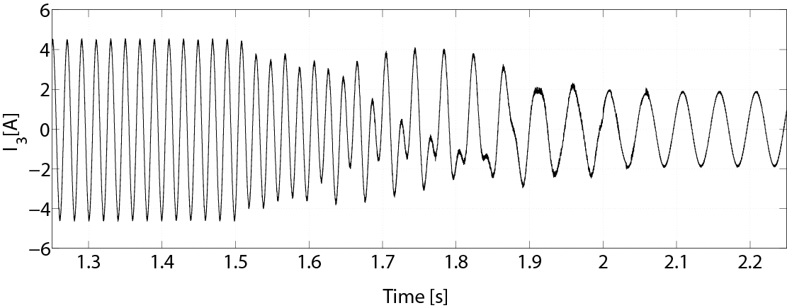
Figure 1: Simulated line current under a 500 ms pole transition beginning at 1.5 s
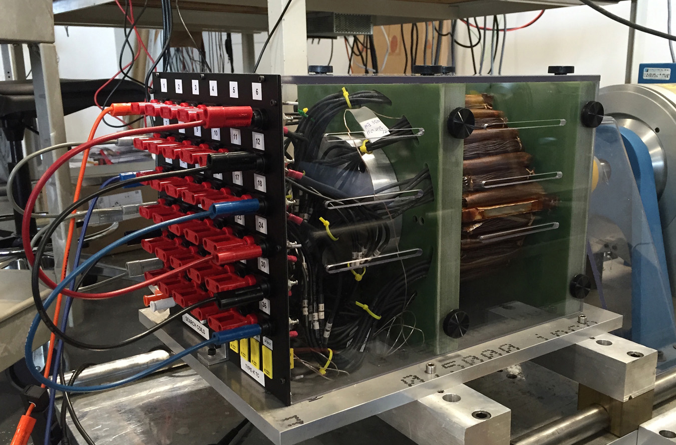
Figure 2: Toroidally-wound induction machine experimental test bed
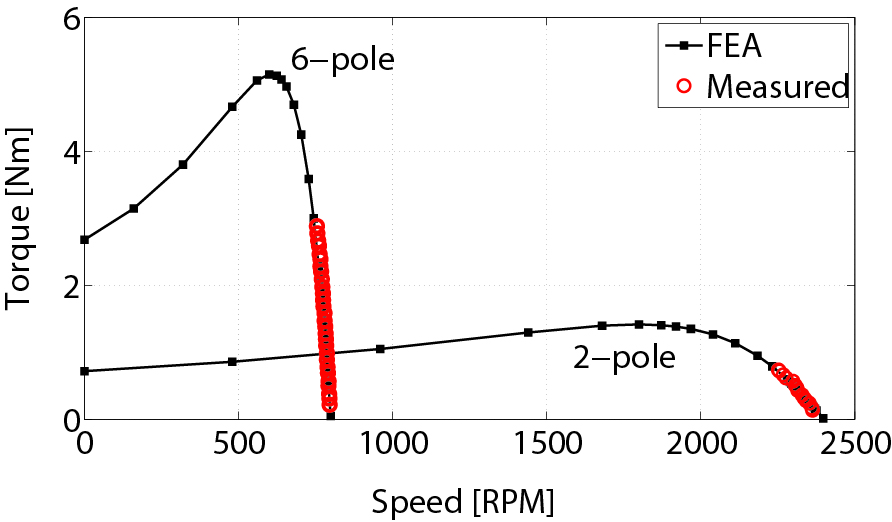
Figure 3: Comparison of FEA and measured torque vs. speed profile for 2-pole and 6-pole operation