Actively Shielded Air-Core Superconducting Machines
MS student David Loder with advisor K. Haran
An important challenge in the design of air-core superconducting machines is containing the magnetic fields within the electric machine. Current solutions result in large reductions of the high power density achievable through the use of superconducting windings. We address this challenge with an actively shielded electromagnet design, an approach commonly used in MRI magnet designs. The topology uses a set of main coils to produce armature MMF (magnetomotive force), while including another set of oppositely excited compensating coils to mitigate the fields radiating outside the machine. This approach eliminates or reduces the use of steel in a passive magnetic shield, allowing for very high-power density machines. The design concept is essentially an inside-out synchronous machine. A rotating, conventional armature is placed inside of the machine. Superconducting field coils, stationary, are placed on the outside, with another set of shielding coils placed further out. Flux densities within a machine cross section are shown in Figure 13. The shielding effect can be seen as the fields are effectively contained. A multi-objective optimization scheme is introduced to minimize two competing objectives—
superconducting coil usage and machine volume. A genetic algorithm is used to compute the pareto-optimal front given a set of constraints. Chiefly, the superconducting coils must lie within the critical surface, including a 50% safety margin. For each candidate design, both the radius at which the field is contained with a thin 5 mm stator yoke and the fundamental radial flux density at the armature are computed. This information is then compared to a baseline design to determine total machine volume. The pareto-optimal front for a 10 MW machine is shown in Figure 14, with the armature flux density mapped in color. This illustrates the best achievable trade-off between superconductor usage and power density. This work is supported by the Grainger Center for Electric Machinery and Electromechanics.

Figure 13: Actively shielded superconducting machine
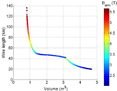
Figure 14: Pareto-optimal front