A Two Time-Scale Approach to Voltage Regulation in Unbalanced Distribution Systems
Brett Robbins with advisor A. Domínguez-García
The introduction of distributed energy resources (DERs), e.g., plug-in hybrid electric vehicles and photovoltaic (PV) installations, in distribution systems results in operational scenarios that these systems were not designed to handle. Interestingly, by properly controlling the power electronic grid interfaces of these DERs, they can provide reactive power support for voltage regulation, thus helping to mitigate the variability introduced by uncontrolled active power injections of certain types of DERs, e.g., PV installations. In order to address the voltage control problem in distribution systems, we envision a two time-scale architecture that classifies voltage control devices as either slow or fast time-scale actuators, with the idea of controlling them separately. Conventional voltage regulation devices, e.g., tap-changing-under-load transformers and switched capacitors, would be considered slow time-scale actuators, whereas power-electronic-interfaced DERs with reactive power provision capability would be the latter. Periodically, the slow time-scale control will dispatch the associated actuators, which would result in some voltage profile. This can be performed based on heuristics associated with the time of day, or the system can be monitored for contingency cases, e.g., system voltages are outside of tolerances. Then, given that fast (and uncontrolled) changes in DER active generation (consumption) might cause the voltage to deviate from the voltage profile set by the slow time-scale optimization, a second optimization or a feedback control scheme executed at regular intervals (e.g., every minute) could be utilized to determine the active/reactive power settings of the DERs. Figures 19 and 20 show the uncontrolled and controlled voltage responses of the IEEE 123-bus unbalanced three-phase distribution system over a 24-hour period, respectively. This research is supported by NSF grant NSF ECCS 09-54420 CAR.
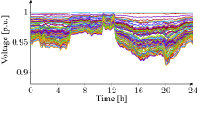
Figure 19: Uncontrolled bus voltages
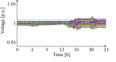
Figure 20: Controlled bus voltages