A Motor-Generator and Supercapacitor Based System for Microgrid Frequency Stabilization — CEME Collaborative Research Project with Oregon State University
Rick Crispo with advisers Ted Brekken and Annette von Jouannen
Energy storage system hardware is shown to achieve microgrid frequency response. A doubly-fed induction generator is coupled with a squirrel cage induction machine as a motor/generator set to deliver an immediate inertial response to a frequency change. An inverter and supercapacitors deliver short-term energy response. Hardware tests show that the rotational inertia provides immediate energy while the control system and supercapacitors give short-term response. The system serves to stabilize frequency in order to improve microgrid service quality and reliability.
A control system is created to monitor grid frequency and activate an inverter to either charge or discharge a bank of capacitors, depending on the measured conditions. For example, when the frequency is measured below 60 Hz, the system injects power into the microgrid to arrest the frequency deviation; above 60 Hz the energy storage system absorbs power. Stabilizing inertia for a microgrid with a high penetration of distributed renewable generation, such as small-scale solar and wind systems, is typically provided by large-scale synchronous generators and is minimal. This hardware adds rotating inertia and short-term energy storage to stabilize the microgrid frequency.

Figure 8: The system delivers frequency response with energy storage from both supercapacitors and real inertia. The microgrid (upper right) is emulated with a high-power motor drive, thus providing precision control over the microgrid frequency.
The frequency stabilization system shown in Fig. 8 consists of a four-pole, 220 kW squirrel-cage induction machine (SCIM), a six-pole, 80 kW doubly-fed induction generator (DFIG) shaft coupled with the SCIM, a transformer to step the voltage down from 480 V to 208 V, a 36 kW grid-tied inverter (GTI) that implements an ac/dc inverter, a dc-link, and a dc/dc converter, and a 0.98 kW-hr (3.6 MJ) supercapacitor energy storage bank. The system presented in Fig. 8 is implemented in the following test. Any value of microgrid frequency may be precisely simulated to demonstrate the system’s response. The value of J, the inertia of the coupled shaft, is made based on a torque response test. A step torque of 20 Nm is applied to the SCIM (with the DFIG unloaded) and the response speed is measured to calculate the value of J and plot its power response.
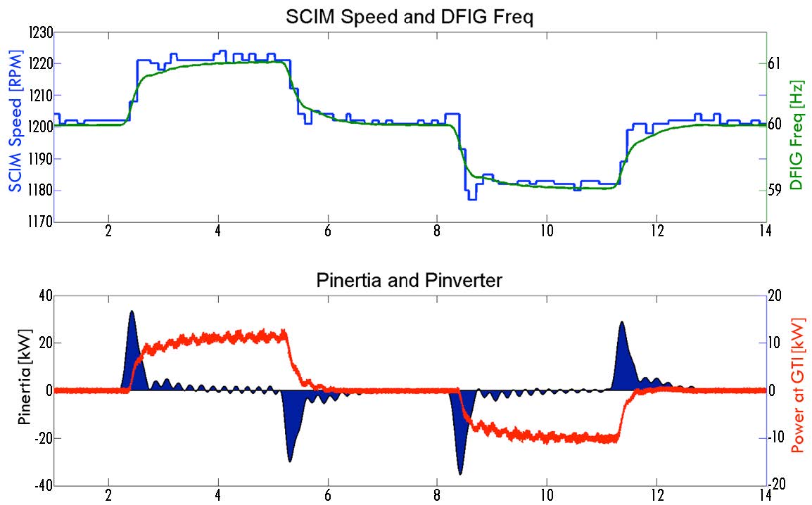
Figure 9: A step change is introduced to the SCIM speed (blue) which changes the DFIG frequency (green). The rotational inertia (dark blue, bottom plot) is shown to deliver energy immediately upon the frequency change, followed by the supercapacitors (red).
The inertia from the motor/generator set can be seen to deliver instantaneous frequency response (Fig. 9). This demonstrates the stabilization effect that rotational inertia has on the grid. It also shows how the energy from the inertia and the supercapacitors is staged as a result of a frequency deviation event. Microgrid operators seeking to increase their use of renewable sources may want to consider adding rotational inertia to their systems to increase reliability and quality.